
Marine housing for a submersible instrument

Inactive Publication Date: 2012-07-26
ISURVEY
View PDF3 Cites 9 Cited by
  • Summary
  • Abstract
  • Description
  • Claims
  • Application Information

AI Technical Summary

Benefits of technology

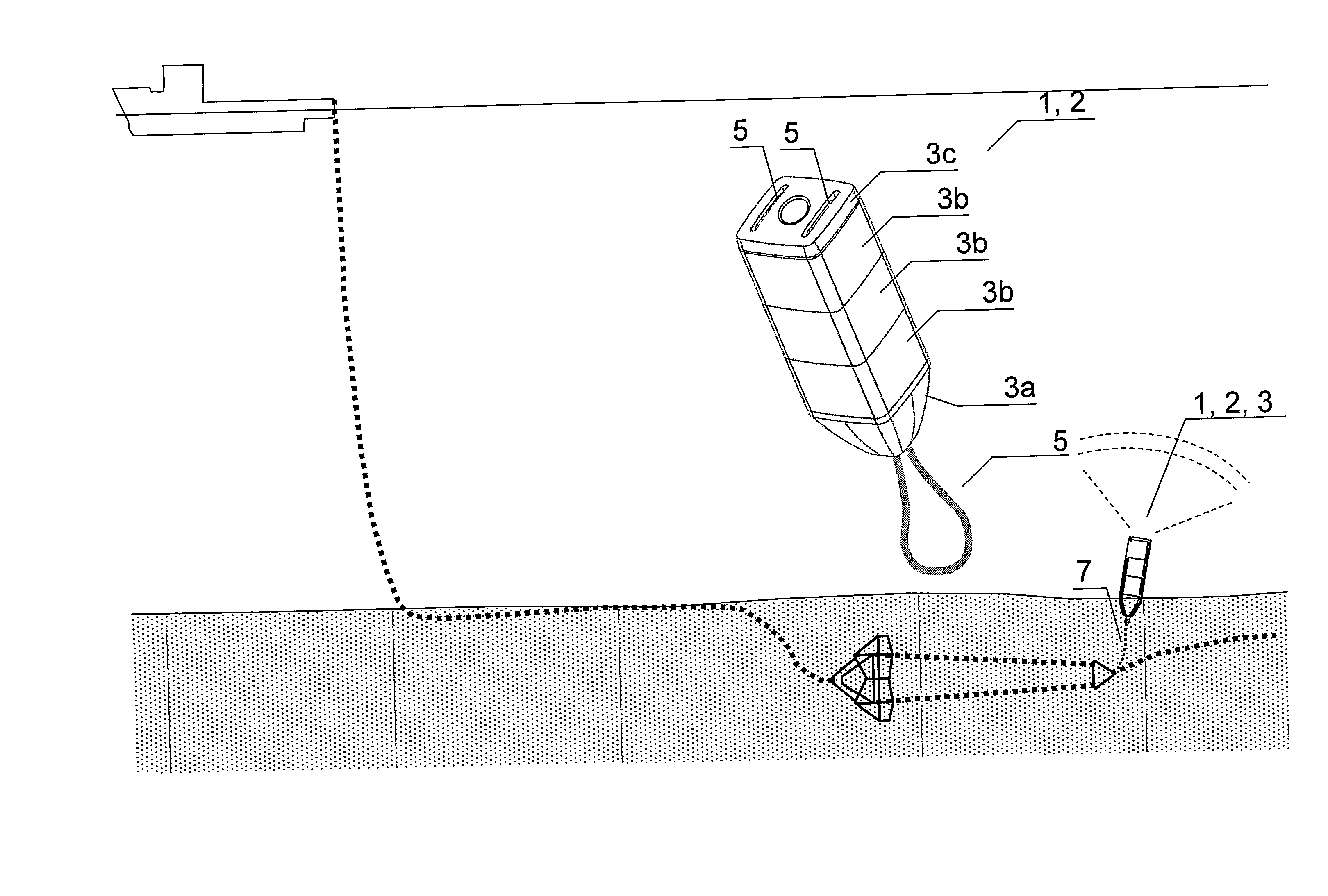
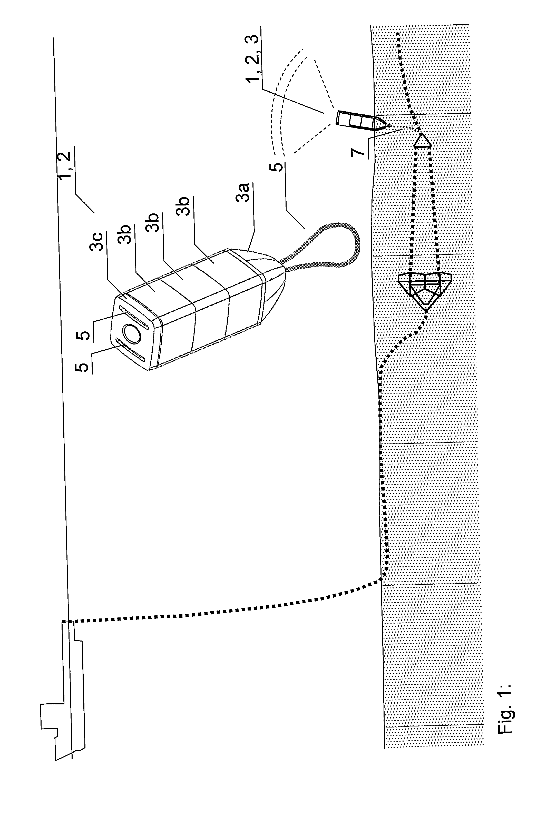
[0008]In a preferred embodiment of the invention two or more of said shell portions (3a, 3b, 3c) are provided with channels (4) for threading or guiding said one or more ropes (5). This stabilizes the shell during assembly and also during use both while in the sea and particularly protects the rope against wear.
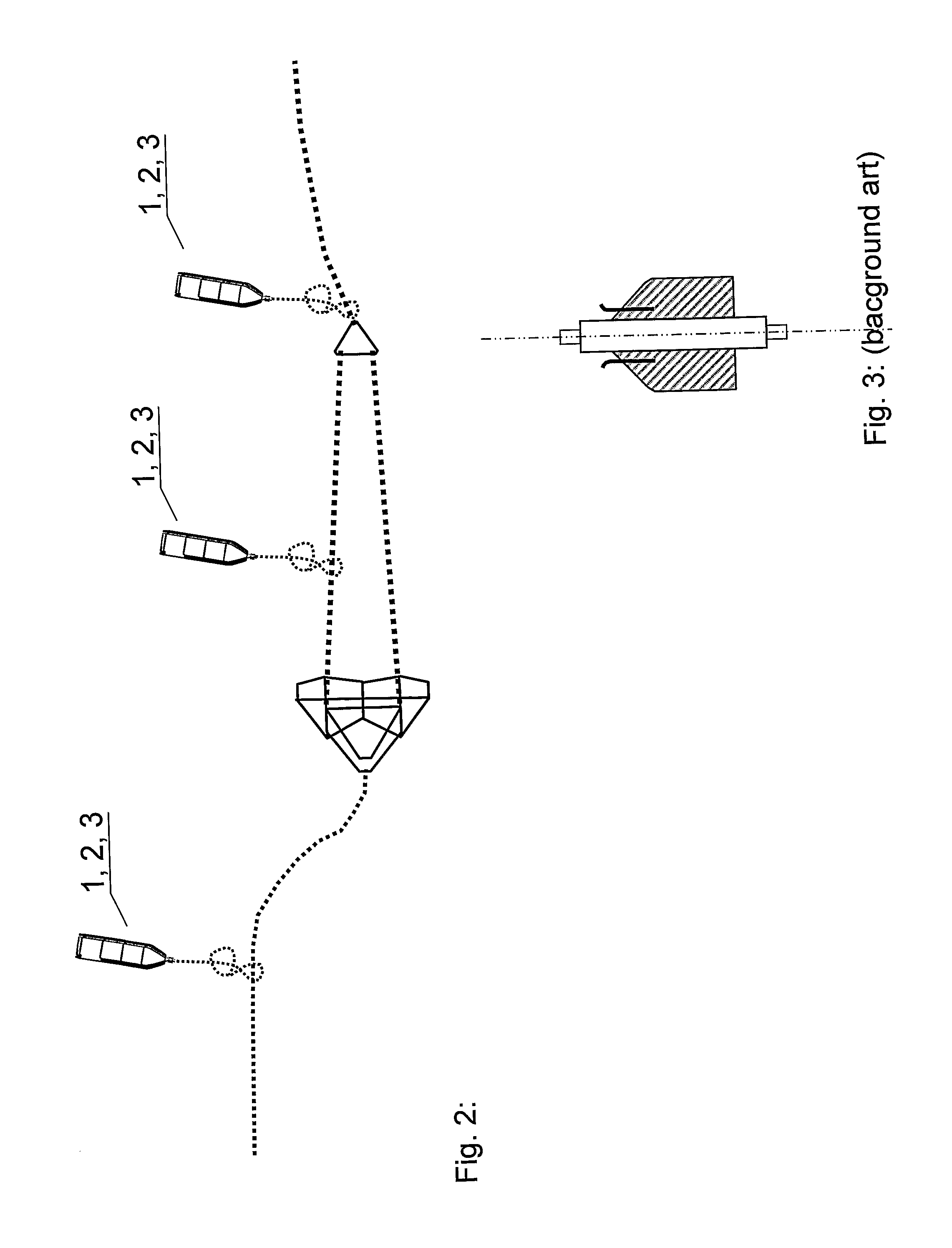
[0012]Connecting a bowline from the shell holding the instrument, generally directly to a part of an anchor line such as a shackle or chain link or triple plate may provide a significant advantage as the housing of the invention allows the instrument to mechanically tolerate being dragged through sediments, thus the anchor may be more precisely positioned. This is an advantage over the prior art instruments which may not withstand being dragged through sediments. It may also be advantageous to connect the shell (1) directly but releasably to the anchor line already on deck of the vessel in order to remain in a controllable position to avoid beatings from chain being dragged along the deck, and subsequently to be extended in the entire length of the bowline when the anchor has landed.BRIEF DESCRIPTION OF THE FIGURES

Problems solved by technology

The connection may be made using a chain portion, which induces a risk of breaking the attachment eye or the end of the instrument while handling the instrument in a deck crane.
The unprotected end portion of the instrument housing is also subject to hitting the deck, chain links, delta plates or any mechanical component during its handling while connected to the anchor or anchor line.
Prior art has the significant disadvantage that the bowline, often a chain or a carabine hook or other metal shackle which is connected directly to one end, usually the lower portion of the instrument, which damages the end of the instrument during deck handling or lowering.
Such a protection housing rigidly attached to the anchor will require modifications to the anchor and will further be subject to strong mechanical forces when the anchor is dragged through the sediments and there is a risk of damage to the sensor and transmitter.
Furthermore, the sensor and transmitter will necessarily end up at the same depth as the anchor, which may be rather deep in the sediments, and may thus not be able to communicate with surface vessels.

Method used


Image

  • Marine housing for a submersible instrument
  • Marine housing for a submersible instrument
  • Marine housing for a submersible instrument

Examples


Embodiment Construction

[0028]The invention will be described in detail with reference to the attached series of drawing Figures and accompanying descriptive text referring to transponder-based underwater location for anchors. The purpose of the invention is however broader, including all type of instruments, and various environments.

[0029]In its broadest definition, the invention is a marine housing for a submersible instrument (2), comprising two or more shell portions (3a, 3b, 3c) for housing and mechanically protecting the instrument (2). Particular features of the invention are represented by the facts that the shell portions (3a, 3b, 3c) are arranged for being assembled as a generally completely enveloping shell (1) forming a cavity (11) for mechanically protecting the instrument (2), and that two or more of the shell portions (3a, 3b, 3c) are provided with a rope (5) or two, or any number of ropes (5) arranged for binding the shell portions (3a, 3b, 3c) together in their assembled positions forming ...


PUM


Abstract

A method for housing a marine submersible instrument includes providing two or more shell portions for forming a complete shell with a cavity, assembling said shell portions around said instrument thereby forming an enveloping shell, and arranging one or more ropes to bind said two or more said shell portions together in their assembled positions about said instrument.

Description

FIELD OF THE INVENTION[0001]The present invention relates to a marine instrument protective housing resistant to mechanical forces such as punching, bending and scraping.BACKGROUND[0002]Underwater structural devices such as large mooring anchors or templates must be lowered and installed to predetermined positions. In order to improve safety, predictability, and speed of operations, the offshore oil and gas industry has grown ever more demanding on the supply of accurate location for underwater equipment. In order to provide such data, during installation, permanent monitoring, or before removal, it has been common to link an acoustic transponder to the submerged equipment, and to locate it thanks to a corresponding transducer on board a related vessel.[0003]However, such transponder, typically a cylinder of a few centimetres diameter and a few decimetres lengths, may be subject to very rough handling. This is in particular the case for transponders designed to locate anchors moorin...

Claims


Application Information

Patent Timeline
IPC IPC(8): H05K5/02
CPCB63B21/22B63B2021/009B63B49/00
Inventor GILDSETH, ROGERSKYRUD, DAG
Owner ISURVEY
Learn More