
Angle-Measuring Device

Active Publication Date: 2012-07-26
DR JOHANNES HEIDENHAIN GMBH
View PDF1 Cites 4 Cited by
  • Summary
  • Abstract
  • Description
  • Claims
  • Application Information

AI Technical Summary

Benefits of technology

[0005]Example embodiments of the present invention provide an angle-measuring device, which is able to satisfy the highest demands with respect to reliability and precision.
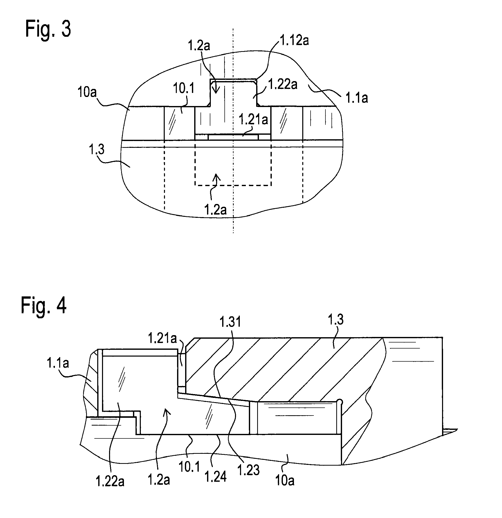
[0018]The positive-locking connection between the connecting element and the carrier element may be provided by a clearance fit or a transition fit. In this manner, it may be ensured that no unacceptable stresses are able to be introduced into the carrier element due to the positive-locking connection. Correspondingly, the positive-locking connection produces no deformations of the carrier element whatsoever, which could lead to a reduction in measuring accuracy.

Problems solved by technology

Correspondingly, the positive-locking connection produces no deformations of the carrier element whatsoever, which could lead to a reduction in measuring accuracy.

Method used


Image

  • Angle-Measuring Device
  • Angle-Measuring Device
  • Angle-Measuring Device

Examples


Embodiment Construction

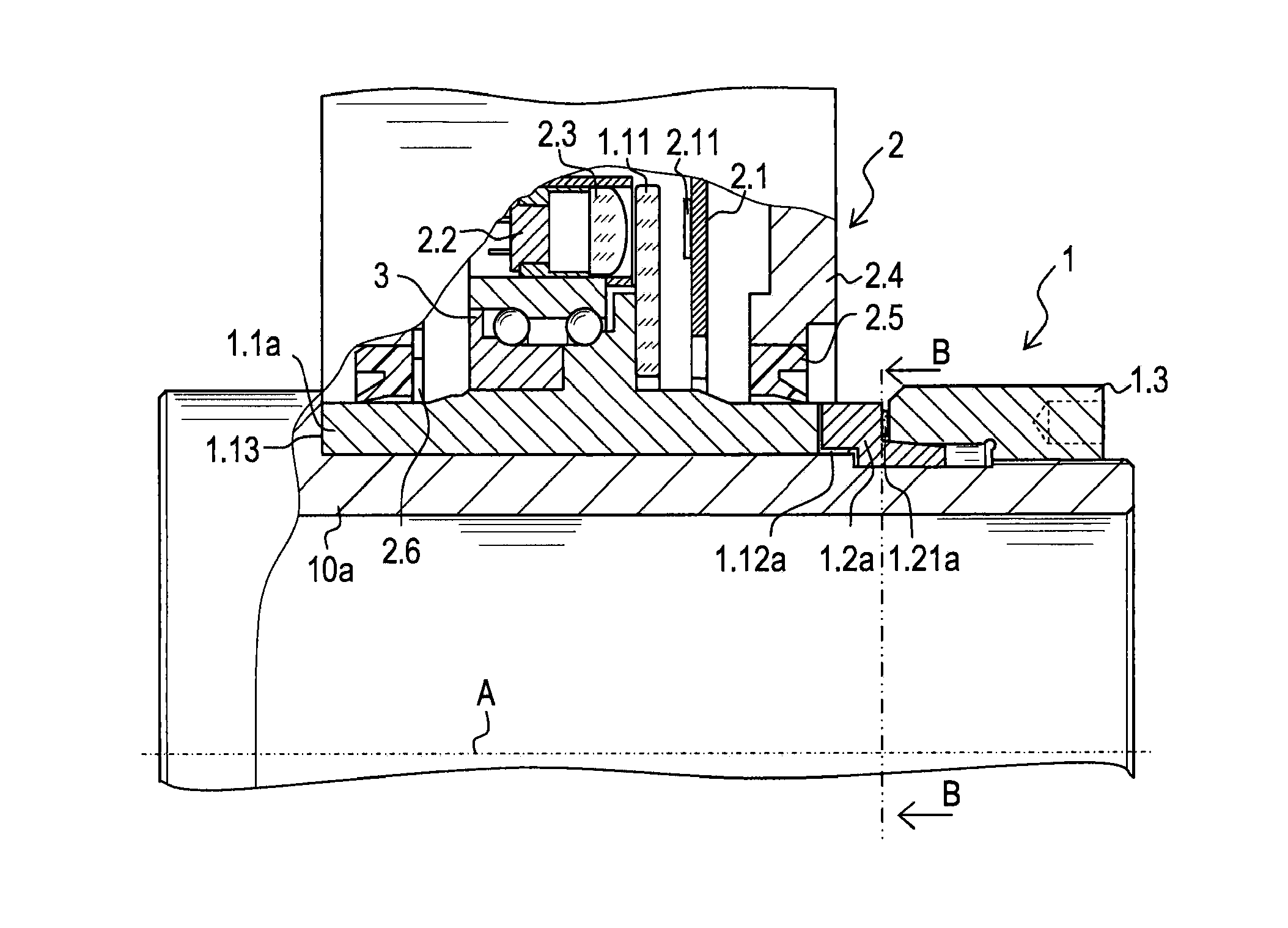
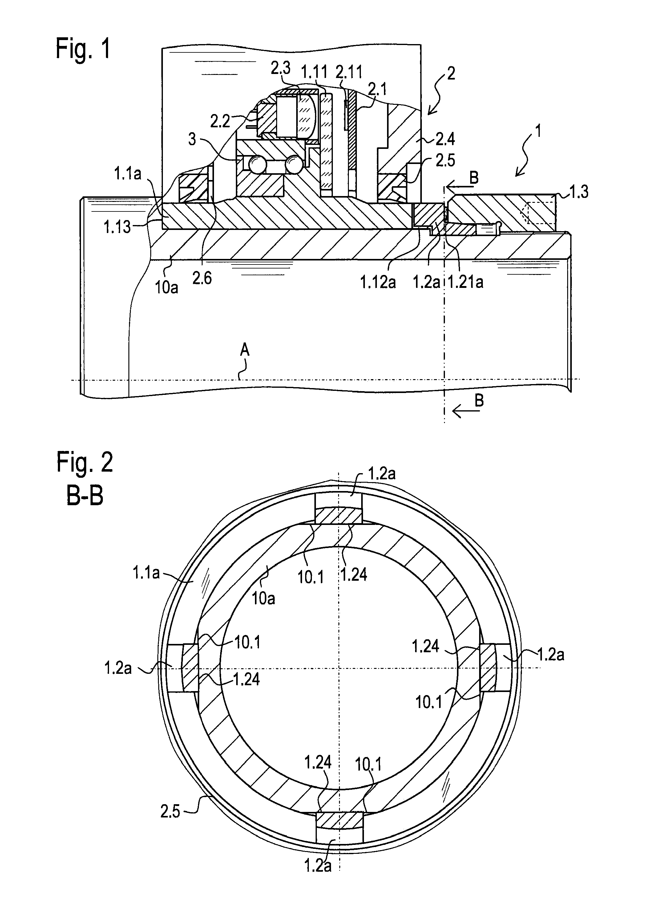
[0035]Hereinafter, the same reference numerals are used for identical components. FIG. 1 shows a partial longitudinal cross-sectional view through an angle-measuring device. The angle-measuring device includes a first group of components, which may be denoted as rotor 1 in the exemplary embodiment illustrated in FIG. 1. Rotor 1 is rotatable about an axis A relative to a second group of components, the second group of components being in the form of, e.g., a stator 2.

[0036]Rotor 1 of the angle-measuring device includes a carrier element 1.1a, e.g., in the form of a hollow shaft whose hollow cylindrical inside space is provided for the torsionally fixed accommodation of a shaft 10a to be measured, so that shaft 10a is enclosed by carrier element 1.1a (see also FIG. 2). A graduation disk 1.11, on which an angle scaling is applied, is secured on rotor 1, i.e., on carrier element 1.1a, by a rigid adhesive connection. Graduation disk 1.11 is produced from a glass material, the angle scali...


PUM


Abstract

An angle-measuring device includes a first group of components and a second group of components that are rotatable relative to each other about an axis. The first group includes a carrier element for enclosing a shaft and on which a graduation disk is secured, a connecting element, and a device for affixing the connecting element relative to the carrier element. The second group includes a sensor element for scanning the graduation disk. The carrier element and the connecting element are arranged such that the connecting element is able to be brought into operative connection with the carrier element so that torque is transmittable with positive locking between the connecting element and the carrier element about the axis. The connecting element is able to be brought into a positive-locking position by axial displacement by the device for affixing the connecting element, and is able to be prestressed radially against the shaft.

Description

CROSS-REFERENCE TO RELATED APPLICATIONS[0001]The present application claims priority to Application No. 10 2011 003 091.3, filed in the Federal Republic of Germany on Jan. 25, 2011, which is expressly incorporated herein in its entirety by reference thereto.FIELD OF THE INVENTION[0002]The present invention relates to an angle-measuring device. For example, the angle-measuring device includes a carrier element and a graduation disk which is secured on it and whose angular position is detectable by a scanning unit having a sensor element.BACKGROUND INFORMATION[0003]Angle-measuring devices of this type are used to measure rotary motions of a shaft over one or more rotations. The rotary motion is determined either incrementally or absolutely. The output measured value as a function thereof, is a sequence of counting pulses, a counter value or a code word. Angle-measuring devices are used particularly for machine tools or machining centers for measuring rotary motions. The determination ...

Claims


Application Information

Patent Timeline
IPC IPC(8): G01B11/26
CPCG01D5/145G01D11/30G01D5/24442
Inventor MITTERREITER, JOHANN
Owner DR JOHANNES HEIDENHAIN GMBH
Learn More