Leading edge device for an aircraft

Inactive Publication Date: 2012-07-26
AIRBUS OPERATIONS LTD
View PDF0 Cites 6 Cited by
  • Summary
  • Abstract
  • Description
  • Claims
  • Application Information

AI Technical Summary

Benefits of technology

[0010]According to the present invention there is provided a leading edge section of an aircraft wing, the section comprising a main wing body portion, a droop nose high-lift leading edge device and a door, which is advantageously moveable to control the amount of airflow in, around or proximate to the droop nose high-lift device. In an embodiment of the invention, the droop nose device is associated with a door that provides control over the injection of air into the boundary layer on the upper surface of the wing. Such control may be useful in facilitating efficient operation of the droop nose device in different high-lift configurations and / or flight conditions as will be explained in further detail below.
[0012]The air flow region is preferably so configured and arranged that, in use, air flowing from the air flow region first flows onto the upper surface of the wing at a position between the fore region of the droop nose high-lift device and the aft region of the main wing body portion, preferably first flowing onto the upper surface of the wing at a position at or near the junction between the droop nose high-lift device and the main wing body portion. Preferably, the wing is so arranged that at least during certain flight conditions air flows through the air flow region and into a boundary layer on the upper surface of the wing. The air flow region may extend from an entrance to an exit. The air may exit the air flow region in a direction substantially parallel to the local shape of the upper surface of the wing. Injecting air onto the upper surface of the wing, or more preferably injecting air into the boundary layer on the upper surface of the wing, introduces extra momentum to the boundary layer. Mixing high-energy flow (extra momentum) into the relatively slow-moving air of the boundary layer energises the boundary and may reduce its susceptibility to separation from the aerofoil surface. Injecting air flow into the boundary layer may therefore allow the aircraft to achieve an increase in the maximum achievable lift coefficient, hence reducing stalling speed.
[0018]The door may be so arranged that, at least when the droop nose high-lift device is in the first deployed position, the door is moveable to a closed position and / or to one or more open positions. When the door is in its closed position, air may be substantially prevented from flowing via said air flow region. The door when open may increase drag whilst enhancing available lift. The door when closed may therefore generate less drag when open. Being able to close the door and generate less drag may be of benefit during take-off for example. The door may be arranged to act, when open and during flight, to divert air to flow via the air flow region onto the upper surface of the main wing body portion. The door may for example be arranged to act as an air scoop. The position of the door may be controlled to be one of many different open positions. The position of the door may therefore be adjusted to provide aerodynamically efficient diversion of air into the air flow region. Arranging the door for pivoting movement may assist in enabling the door to act as an air diverting means.
[0024]The present invention also provides a method of operating a droop nose high-lift device. The method may include a step of providing an aircraft including an aircraft wing according to the present invention. The method may be in the form of operating an aircraft, the aircraft having a wing comprising a main wing body portion and a droop nose high-lift device mounted fore of the main wing body portion. The step of operating the aircraft includes moving the aircraft relative to the surrounding air as is the case during take-off or landing. The method may comprise a step performed during operation of moving the droop nose high-lift device to a first deployed position to define an air flow region between the droop nose high-lift device and the main wing body portion. The method may comprise a step performed during flight of moving the door to cause air to flow from beneath the wing, through the air flow region, and onto the upper surface of the main wing body portion. The method may be performed such that the droop nose high-lift device is moved to its first deployed position and the door is opened, the open door and air flow region act to create an air circulation effect around the outer end of the droop nose high-lift device. This air circulation effect may be similar to the air circulation effect caused by a deployed / slotted slat, thus reducing the loading of the wing leading edge for example. Such a reduction in loading may reduce the tendency of the wing flow to separate in the area that is critical to maximising the maximum lift coefficient, CLmax, thus increasing the maximum incidence of the wing and the high-lift performance of the aircraft.

Problems solved by technology

Mixing high-energy flow (extra momentum) into the relatively slow-moving air of the boundary layer energises the boundary and may reduce its susceptibility to separation from the aerofoil surface.

Method used


Image

  • Leading edge device for an aircraft
  • Leading edge device for an aircraft
  • Leading edge device for an aircraft

Examples


Embodiment Construction

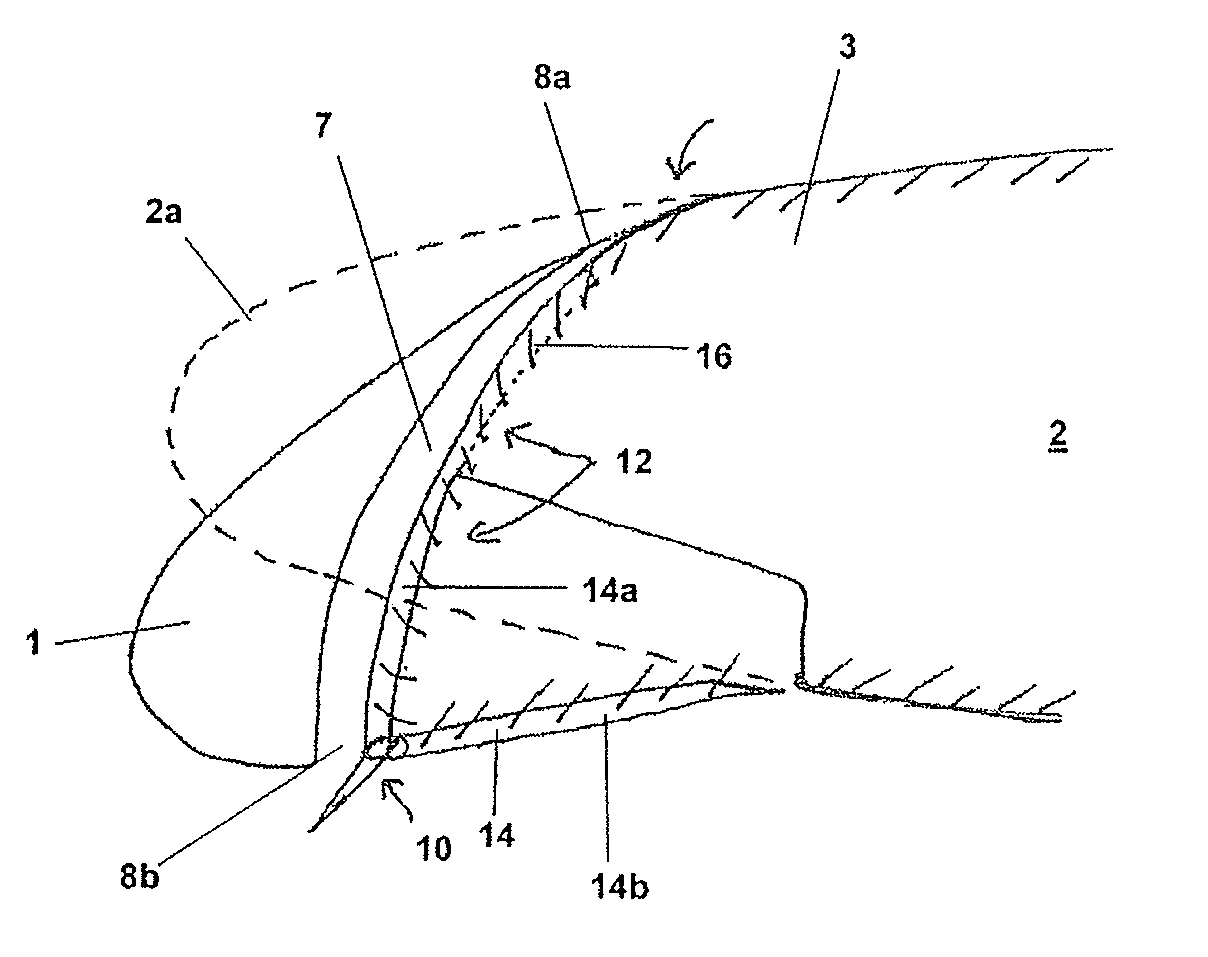
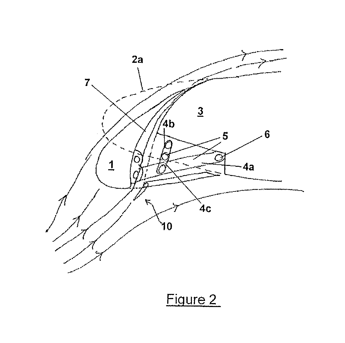
[0052]FIGS. 1 and 2 show a droop nose high-lift device 1 which forms part of a wing 2, only the leading edge section of which being shown. It will be appreciated that the wing section illustrated could form part of a larger component for example the whole of the wing or could be a separately manufactured section of wing that is fitted to the rest of the wing during assembly of the aircraft. The rest of the wing may for example be as shown in the aircraft illustrated in FIG. 5. The droop nose high-lift device 1 is attached to the adjacent main wing body portion 3, via a hinge mechanism 5 (shown in FIG. 2). The droop nose high-lift device 1 is moveable between a stowed position and two principal deployed positions. Both Figures illustrate the droop nose high-lift device 1 in the first deployed position adopted during landing, which in this embodiment is achieved by means of a 25 degree downward rotation of the droop nose high-lift device from the stowed position. During take-off, the ...


PUM


Abstract

A leading edge section of an aircraft wing comprises a main wing body portion, a droop nose high-lift device mounted adjacent to the fore region of the main wing body portion, and a door. The droop nose high-lift device is moveable between a stowed position and a first deployed position. When the droop nose high-lift device is in the first deployed position and the door is in an open position, an air flow region is exposed such that, during use, air flows through the air flow region from the lower surface to the wing upper surface of the wing. The door is also arranged to be moved during flight to control the amount of airflow through said air flow region.

Description

BACKGROUND OF THE INVENTION[0001]The present invention concerns aircraft, and in particular, but not exclusively to those having high-lift leading edge devices and to the use thereof. The invention also concerns an aircraft wing having such a high-lift leading edge device, an aircraft wing section, high-lift leading edge devices per se, to a method of operating an aircraft and to other related aspects.[0002]High-lift leading edge devices are often used on an aircraft to increase the available maximum lift, particularly during take-off and landing.[0003]Two known high-lift leading edge devices are the slat and the droop nose high-lift device.[0004]Slats are generally moveable between a retracted position in which the slat is located against the leading edge of the wing and a deployed position in which the slat is deployed downwards and forwards away from the main portion of the wing. Air flows around the deployed slat such that the slat has its own flow field. The interaction between...

Claims


Application Information

Patent Timeline
IPC IPC(8): B64C3/50
CPCB64C3/50Y02T50/32Y02T50/145B64C9/26Y02T50/10Y02T50/30
Inventor DODD, DANIEL
Owner AIRBUS OPERATIONS LTD
Why Eureka
Try Eureka