
Beverage dispensing apparatus

a beverage and apparatus technology, applied in the direction of liquid dispensing, liquid/fluent solid measurement, volume measurement, etc., can solve the problems of difficulty in satisfying the home user's keg refilling under adequate pressure, tap pressure or gravity is often insufficient to provide a satisfying pour, etc., to reduce the volume of the bag, reduce the pressure, and the effect of volume reduction

Active Publication Date: 2012-07-26
COOPERS BREWERY
View PDF12 Cites 55 Cited by
  • Summary
  • Abstract
  • Description
  • Claims
  • Application Information

AI Technical Summary

Benefits of technology

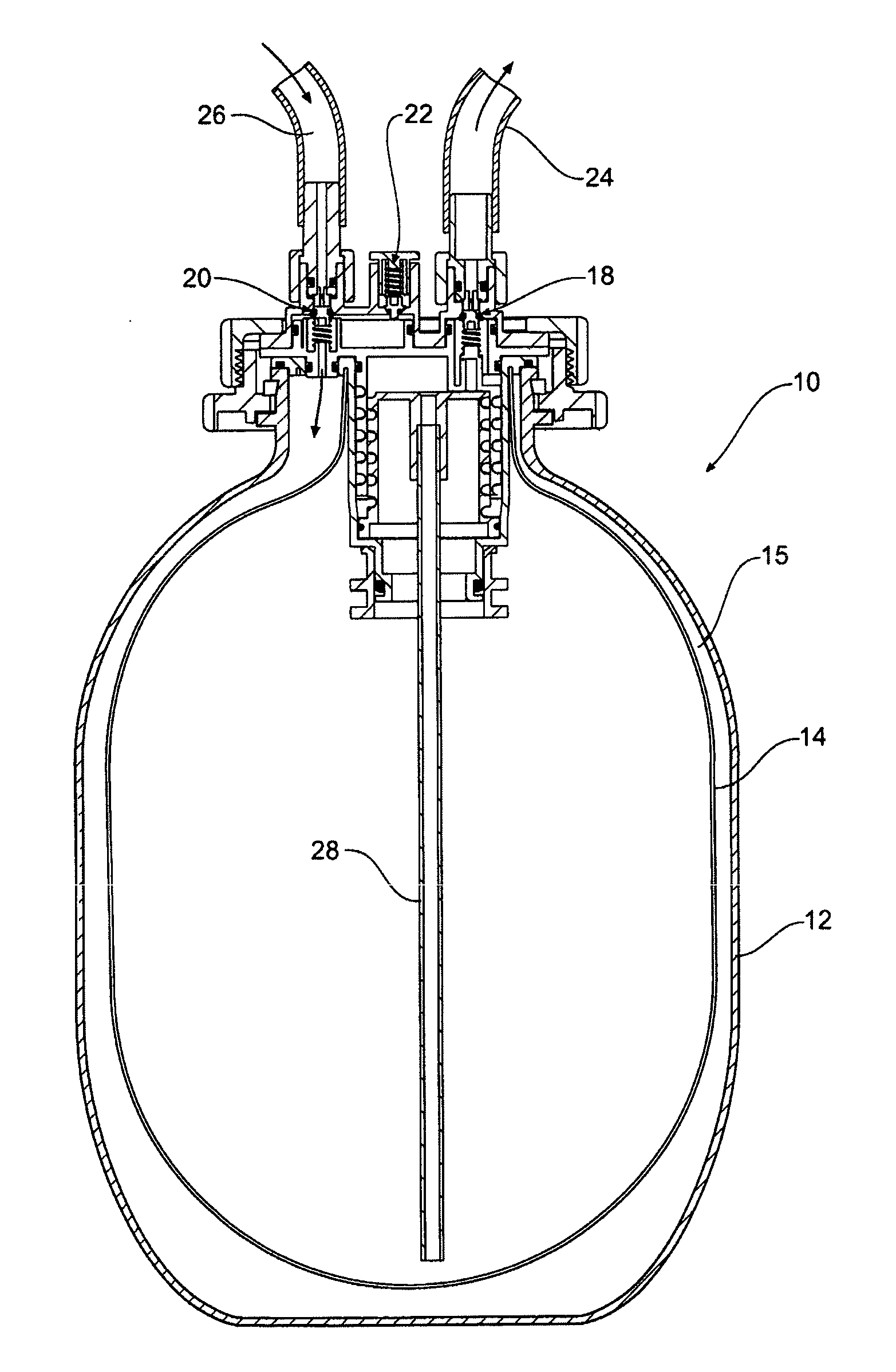
[0013]For dispensing the beverage from the keg assembly, the keg assembly can be connected to a dispensing device, which provides a tap having a tap handle and a tap faucet, and a gas compressor. A beverage conduit connects the beverage outlet to the tap, and a gas conduit connects the gas compressor to the gas valve. The gas compressor maintains the pressure in the sealed cavity, to a pressure above the external atmospheric pressure. Upon operation of the tap handle, the beverage is forced out of the collapsible container, flows through the beverage outlet and is dispensed via the tap faucet. This reduces the volume of the bag, reducing the pressure in the cavity, which in turn triggers a pressure activating switch for the compressor. Gas from the compressor is accordingly forced through the gas valve, into the sealed cavity, which maintains the pressure within the cavity and (at least whilst the tap is open) continues to collapse the collapsible container. In this way, the beverage is squeezed out of the collapsible container, through the beverage outlet, to the tap faucet.
[0014]The beverage within the collapsible container is kept at a relatively constant pressure—as the beverage is dispensed, the container collapses and its volume accordingly decreases. This helps maintain carbonation within carbonated beverages such as beer, and also helps ensure that the dispensing pressure allows for a satisfying pour.
[0017]In a second aspect of the present invention, there is provided a dispensing device for connection to the keg assembly of the first aspect of the present invention. The dispensing device may comprise a tap having a tap handle and a tap faucet, the tap connected to the beverage outlet of the keg assembly, and a gas compressor in fluid connection with the gas valve of the keg assembly. A pressure activating switch may be provided which triggers the compressor upon a decrease of pressure within the cavity, such that as the beverage is dispensed, the compressor forces gas through the gas valve of the keg assembly. It accordingly helps force the beverage through the beverage outlet of the keg assembly to the tap faucet, and maintain the beverage pressure within the collapsible container. The dispensing device may also chill the beverage.

Problems solved by technology

However, these mini-kegs also often have problems in that the pressure provided by the tap or by gravity is often insufficient to provide a satisfying pour.
Furthermore, reuse of a mini-keg would often exacerbate the problem of the difficulty in maintaining pressure within the mini-keg—it may be difficult for a home user to satisfactorily refill the keg under adequate pressure.

Method used


Image

  • Beverage dispensing apparatus
  • Beverage dispensing apparatus
  • Beverage dispensing apparatus

Examples


Embodiment Construction

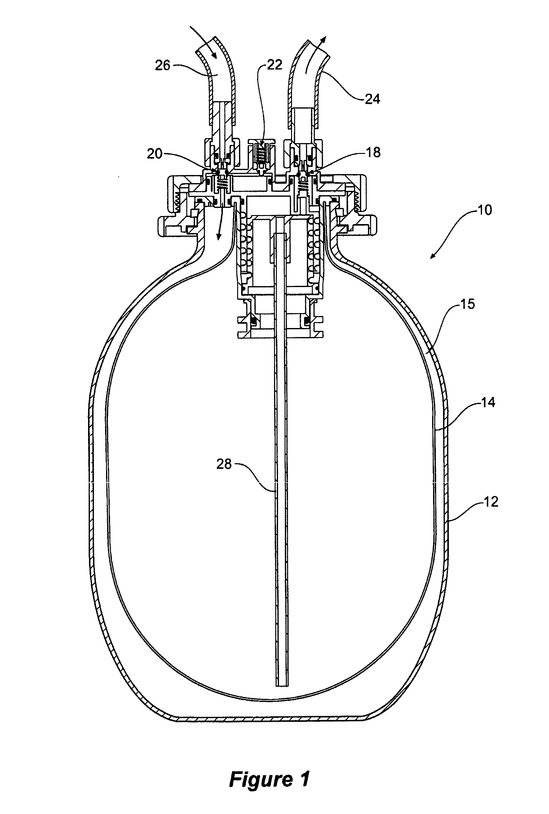
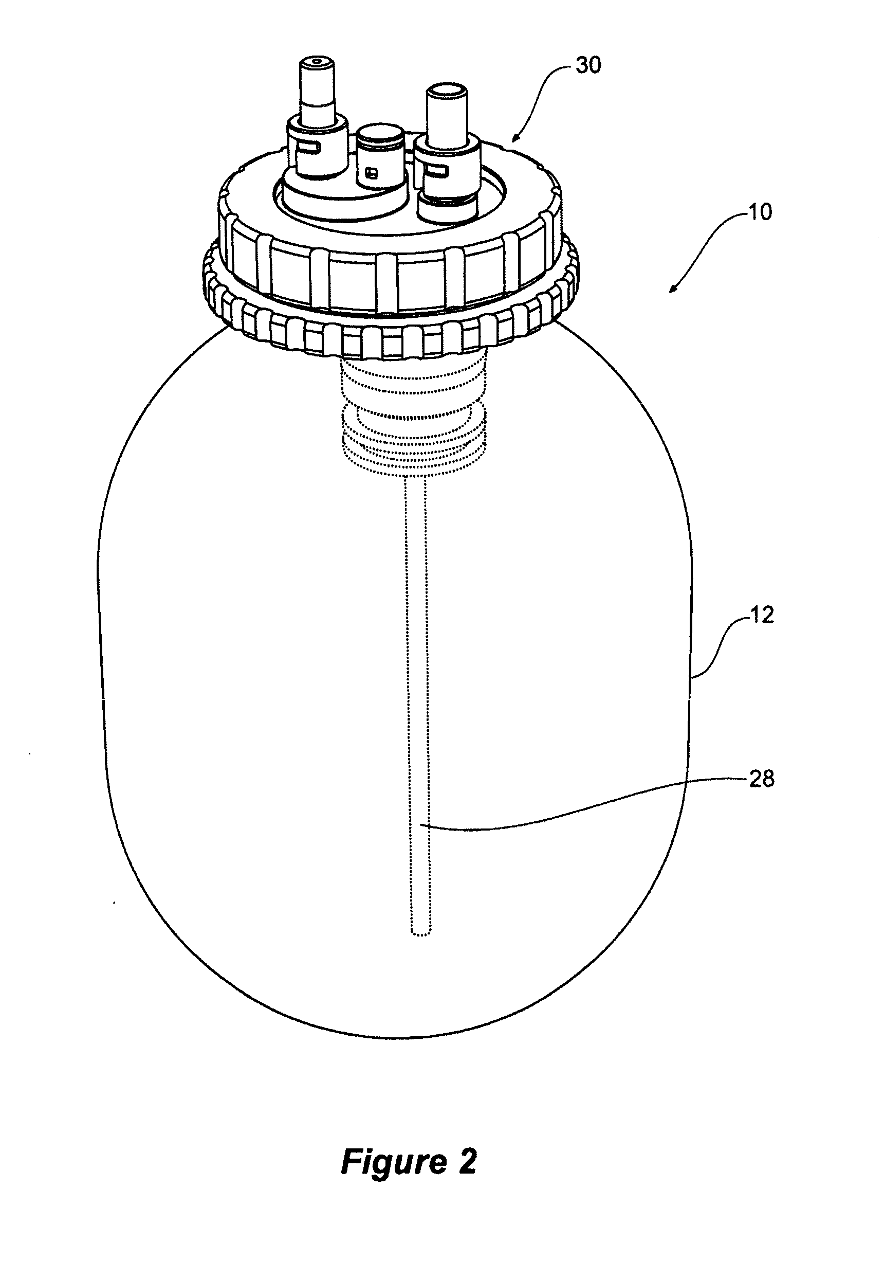
[0036]Referring to the figures, there is shown a keg assembly 10 according to an embodiment of the present invention. This keg assembly 10 is intended to be able to contain approximately 5 litres of beverage, although obviously the volume may vary within the scope of the present invention.

[0037]FIG. 1 provides a general view of a keg assembly 10 according to an embodiment of the present invention. The keg assembly 10 comprises an outer shell 12, and a bag 14 within the outer shell 12 which provides a collapsible container for beer. A sealed cavity 15 is defined between the outer shell 12 and the bag 14. The keg assembly 10 further comprises a cap assembly 30 having a beverage valve 18, a gas valve 20 and a relief valve 22. The outer shell 12 may be formed of common polyethylene teraphthalate (PET), and the bag 14 may be a simple plastic bag (e.g. commercial drinking water cask bladder).

[0038]The beverage valve 18 allows the beverage to exit the bag 14 to a beverage tube or conduit 2...


PUM

PropertyMeasurementUnit
Pressureaaaaaaaaaa
Flow rateaaaaaaaaaa

Abstract

The present invention relates to a refillable keg assembly for use in dispensing beverages, in particular beer. The keg assembly comprises an outer shell, and a collapsible container for holding the beverage, positionable within the outer shell. A sealed cavity is defined between the outer shell and the collapsible container. A beverage outlet from the collapsible container enables beer to be dispensed from the keg assembly, and a gas valve allows gas to enter the cavity. The pressure in the container is maintained above atmospheric pressure, and when dispensing the beverage, pressure in the cavity collapses the collapsible container and forces the beverage out through the beverage outlet. A gas compressor is connected to the gas valve, and is activated by a pressure switch to maintain the pressure within the cavity. To refill the keg assembly, the collapsible container can be replaced, and a new collapsible container filled whilst within the outer shell.

Description

PRIORITY CLAIM[0001]This application claims priority from Australian Patent Application No 2009903325, the entire contents of which are hereby incorporated by reference.FIELD OF THE INVENTION[0002]The present invention relates to container and apparatus for dispensing a beverage. The present invention will be described with particular reference to dispensing beer, although the invention may have broader application.BACKGROUND OF THE INVENTION[0003]Carbonated beverages, such as beer, are commonly stored in large volume containers and then dispensed to glasses or cups for consumption. Beer is often stored under pressure in a large volume metal keg (e.g. 50 litres). Kegs are artificially pressurised after fermentation using carbon dioxide, or sometimes a mixture of carbon dioxide and nitrogen gas. A typical keg has a single opening in the centre of its top, to which a flow pipe is attached. Pressure in the keg then drives the beer to the dispensing tap.[0004]Smaller volume kegs (e.g. 5...

Claims


Application Information

Patent Timeline
IPC IPC(8): B67D7/60B65D83/00B67D7/80B65B1/04B67D3/00G01F11/00
CPCB67D1/0462B67D2001/0828B67D1/0831
Inventor BURGE, PAUL ANDREWWALLACE, ALLAN K.HARRIS, SCOTT
Owner COOPERS BREWERY
Learn More