Eureka AIR delivers breakthrough ideas for toughest innovation challenges, trusted by R&D personnel around the world.

Multi-Rate Implementation Without High-Pass Filter

a multi-rate implementation and high-pass filter technology, applied in the field of digital signal filtering, can solve problems such as constant group delay, and achieve the effect of reducing computational requirements and eliminating high-pass filtering

Active Publication Date: 2012-07-19
AUDYSSEY LABORATORIES
View PDF6 Cites 31 Cited by
  • Summary
  • Abstract
  • Description
  • Claims
  • Application Information

AI Technical Summary

Benefits of technology

This patent describes an improved way to filter that reduces computation needed while still achieving good results. It uses a technique called linear phase FIR filters with constant group delay. By copying and processing inputs in two different ways, one at a higher rate than the other, this approach avoids the requirement for certain types of filtering often necessary in previous methods. Users can also set specific performance standards like minimal resolution or maximum accuracy. Overall, this new method simplifies the process of creating efficient filters without sacrificing quality.

Problems solved by technology

This patent discusses improving the accuracy of low frequency filtering in digital signals while reducing the necessary processing power. Single finite impulse response (FIR) filters can perform high quality filtering with minimal distortion, but they require very long delays when applied to broadband signals. Multi-rate filters offer an alternative solution that separates the signal into different frequency ranges and uses shorter FIR filters on each range. However, current techniques like using linear phase FIR filters result in increased computational load. Therefore, this technical problem presents how to effectively implement higher precision filtering without adding excessive computing resources.

Method used


Image

  • Multi-Rate Implementation Without High-Pass Filter
  • Multi-Rate Implementation Without High-Pass Filter
  • Multi-Rate Implementation Without High-Pass Filter

Examples


Embodiment Construction

[0032]The following description is of the best mode presently contemplated for carrying out the invention. This description is not to be taken in a limiting sense, but is made merely for the purpose of describing one or more preferred embodiments of the invention. The scope of the invention should be determined with reference to the claims.

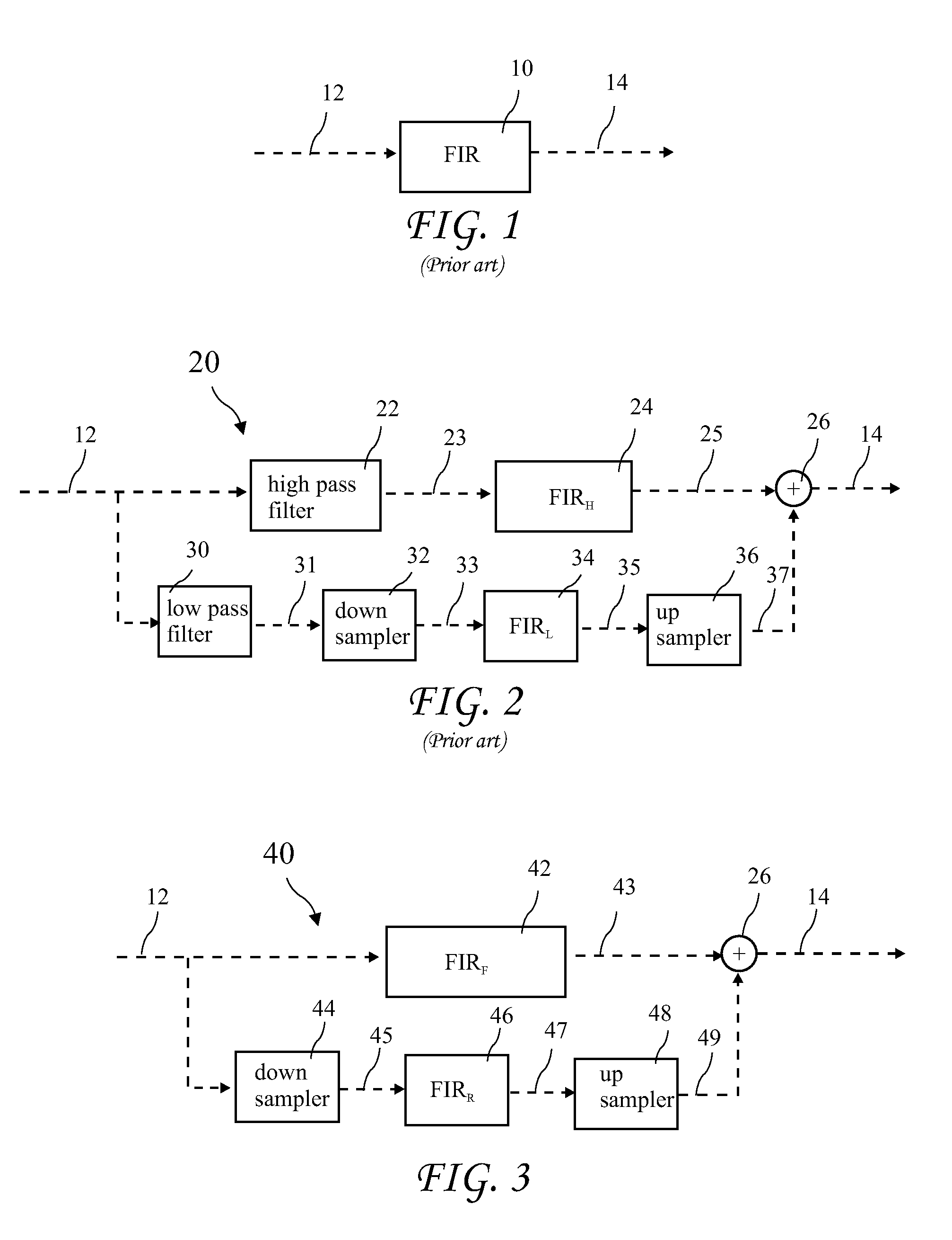
[0033]A prior art digital filter with a single Finite Impulse Response (FIR) filter (the target FIR filter) 10 applied to an input signal 12 to produce a filtered signal 14. The Target FIR filter 10 must perform operations at the high sample rate of the input signal 12 and also be of sufficient length to provide accurate filtering to low frequency components in the input signal. The resulting processing may require a very large number of operations at the high sample rate.

[0034]A prior art multi-rate digital filter 20 with two parallel FIR filters, FIRH 24 and FIRL 34, applied to the input signal 12 is shown in FIG. 2. The input signal 12 is proce...


PUM


Abstract

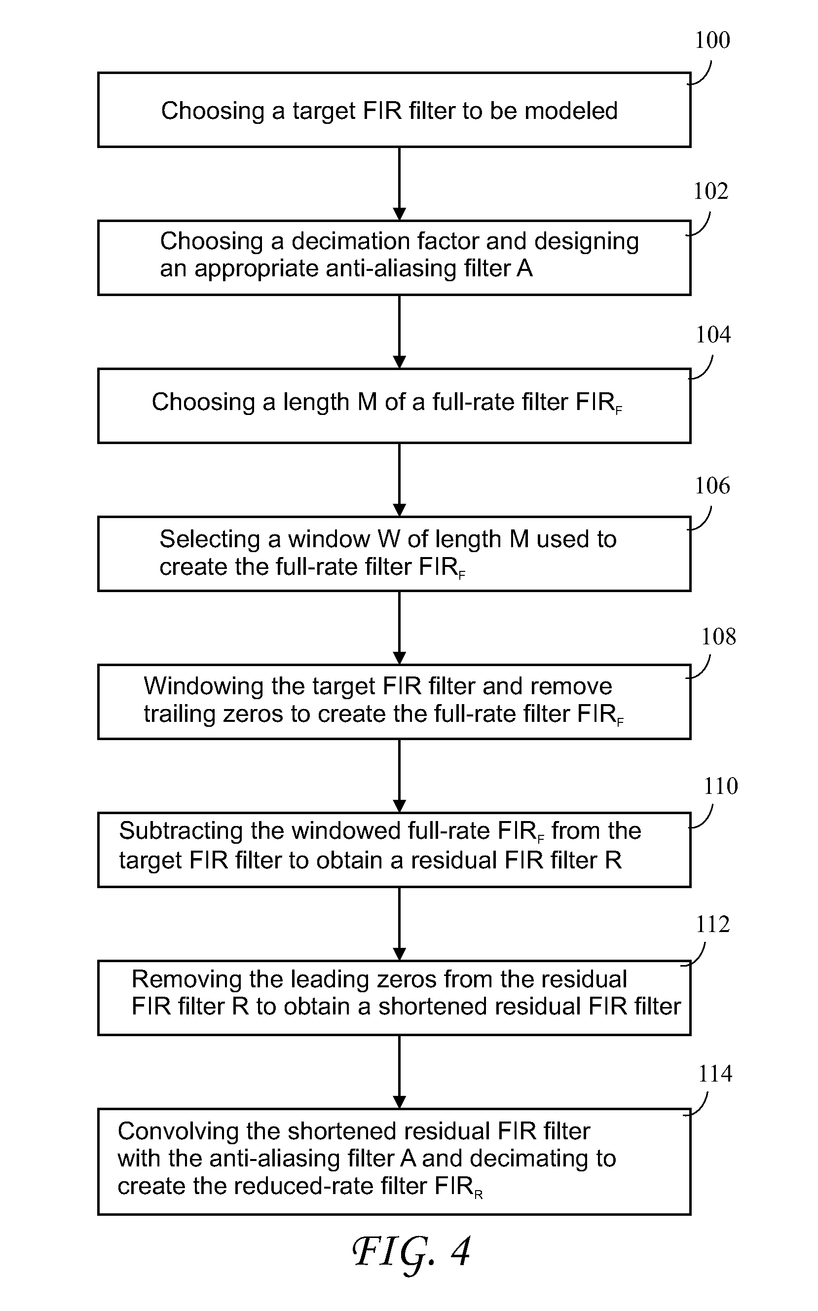
A filtering method approximates a target Finite Impulse Response (FIR) (or transversal) filter and reduces computational requirements by eliminating high pass filtering required by known multi-rate filters. An input signal is copied into two identical signals and processed in parallel by a full-rate path, and by a reduced-rate path. Parallel filters are computed and applied in each path, the reduced-rate signal is up-sampled, and the two signals summed. The high pass filter required by known multi-rate filters is eliminated and the low pass filter in the prior art is implicit in a down sampling. Linear phase FIR filters are used for down and up sampling, resulting in constant group delay. Added benefits include the option of zero added latency through the filtering and the constant group delay added to the target FIR. The user may choose criteria such as minimum resolution in each band.

Description


Claims


Application Information

Patent Timeline
Owner AUDYSSEY LABORATORIES
Why Eureka
Eureka Blog
Learn More