
Substrate structure for semiconductor device fabrication and method for fabricating the same

a technology of semiconductor devices and substrates, applied in the direction of semiconductor devices, basic electric elements, electrical equipment, etc., can solve the problems of no solution capable of increasing the utilization rate of wafers, and achieve the effect of improving throughput, increasing surface area, and not increasing the dimensions of said substrates

Inactive Publication Date: 2012-07-19
SUNOVEL SUZHOU TECH
View PDF4 Cites 0 Cited by
  • Summary
  • Abstract
  • Description
  • Claims
  • Application Information

AI Technical Summary

Benefits of technology

This approach effectively increases the surface area that can be processed, improves throughput, and reduces costs by allowing for efficient material deposition and processing on both sides of the strip plate structure.

Problems solved by technology

However, no solutions capable of increasing the utilization rate of wafers have been proposed so far based on the dimensions of existing wafers.

Method used

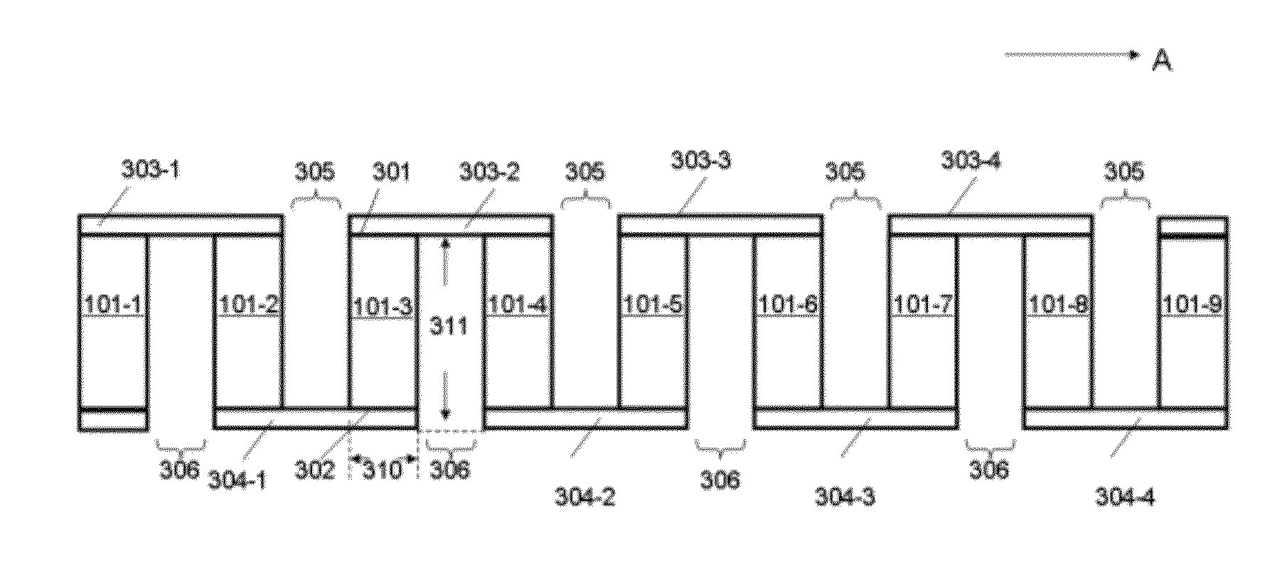
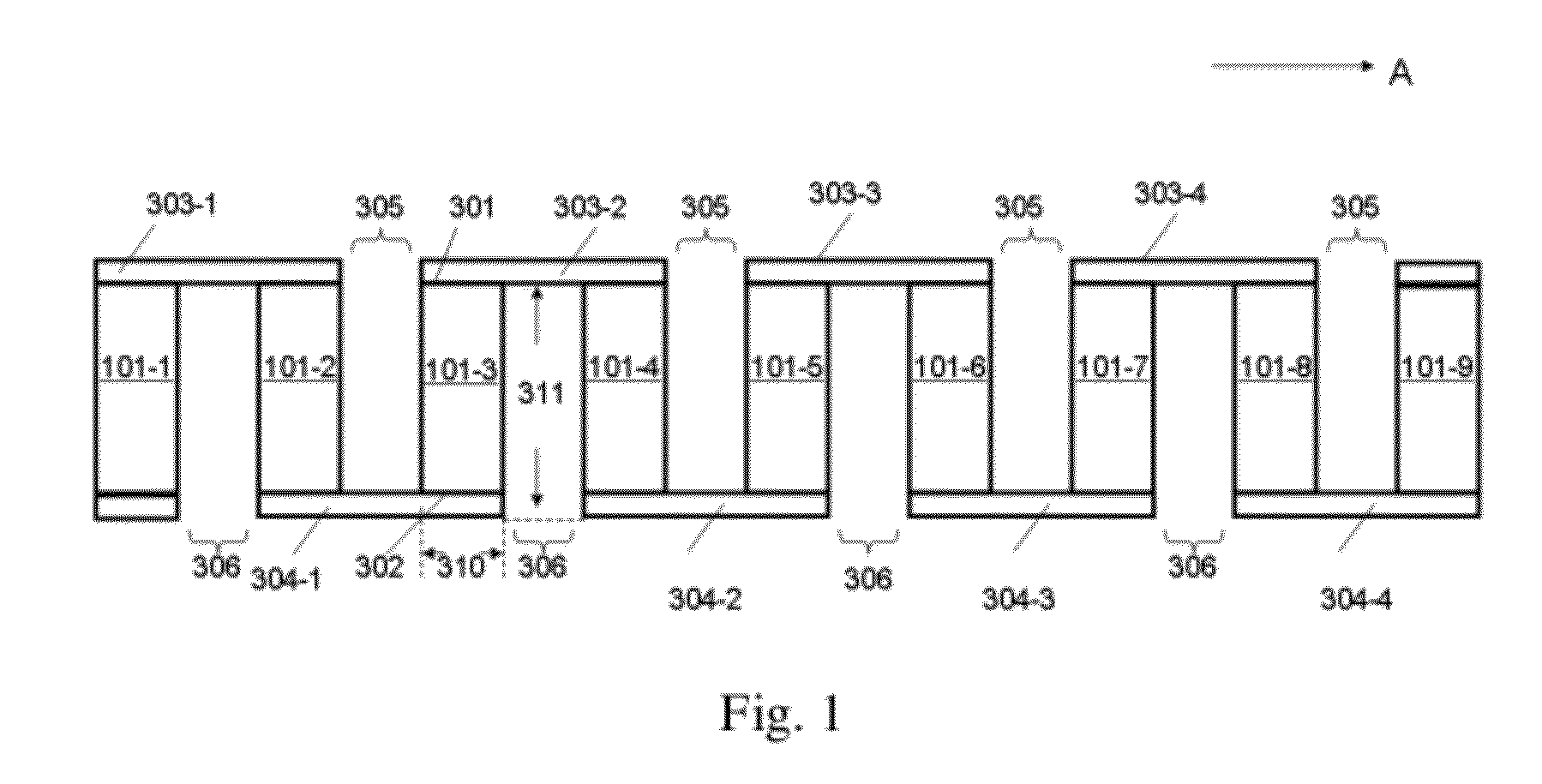
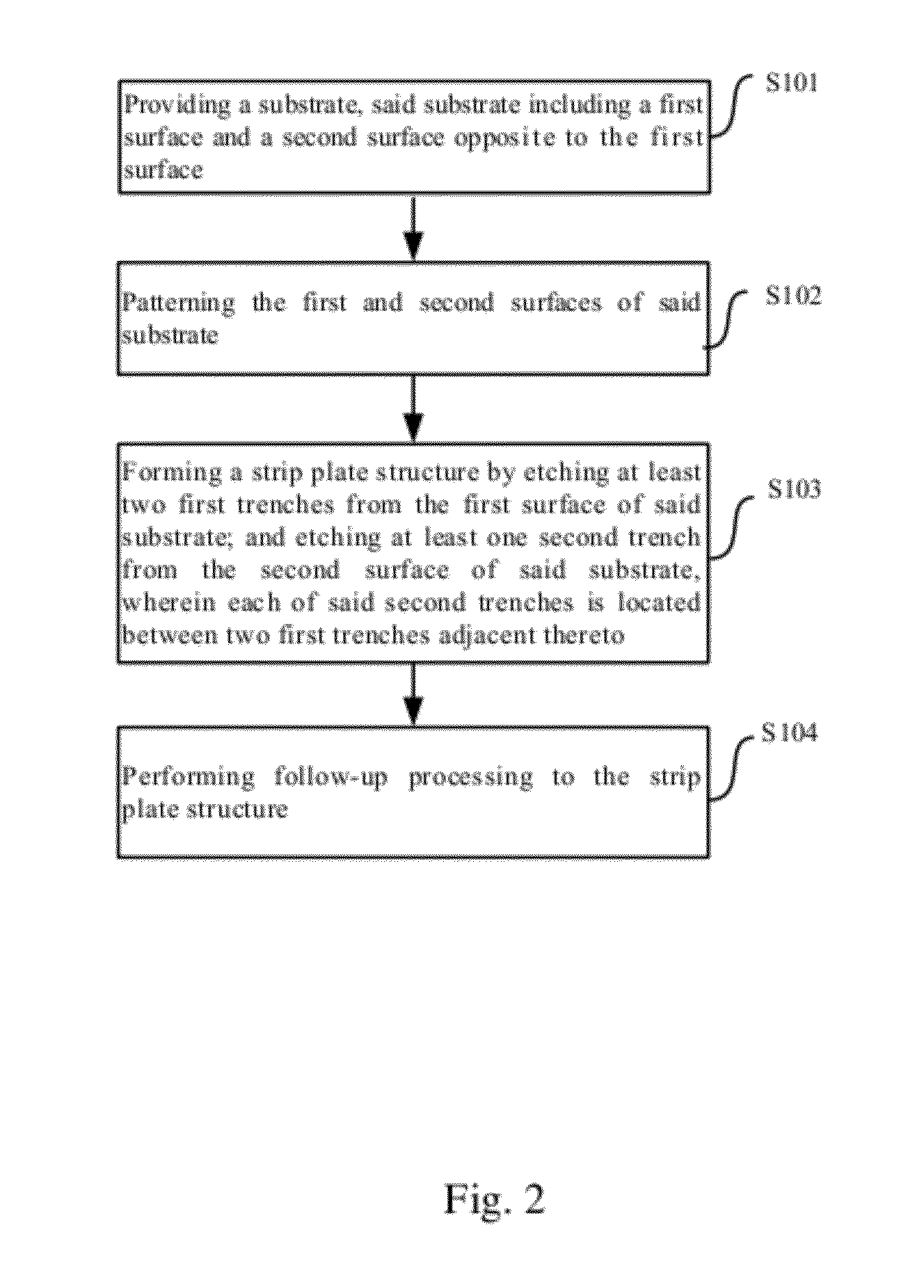

Image

  • Substrate structure for semiconductor device fabrication and method for fabricating the same
  • Substrate structure for semiconductor device fabrication and method for fabricating the same
  • Substrate structure for semiconductor device fabrication and method for fabricating the same

Examples


Embodiment Construction

[0013]Embodiments of the present invention are described in detail in the following text and are illustrated in the drawings, wherein like reference numerals used throughout the description represent like components or components having like functions. The embodiments described in conjunction with the drawings below are merely illustrative and used to only explain the present invention, which cannot be construed as limiting the present invention. The disclosure of the following text provides various embodiments or examples for realizing different structures of the present invention. In order to simplify the disclosure of the present invention, component parts and configurations of specific examples are described in the following text. Of course, they are only examples and are not directed to limit the present invention. Furthermore, reference numerals and / or letters may be repeated in different examples of the present invention. Such repetition is for the purposes of simplification ...


PUM


Abstract

The present invention proposes a strip plate structure and a method of manufacturing the same. In one embodiment, the strip plate structure comprises a strip plate array comprising a plurality of strip plates arranged in a predetermined direction with spacing, each of said strip plates including a first surface facing one side direction of the strip plate structure and a second surface facing an substantially opposite side direction of the strip plate structure; and a plurality of strip sheets, each strip sheet alternately abutting either the first surfaces or the second surfaces of two adjacent strip plates.

Description

FIELD OF THE INVENTION[0001]The present invention relates to the field of semiconductor manufacturing. In particular, it relates to a strip plate structure having an enlarged surface area for semiconductor devices and a method of manufacturing the same.BACKGROUND OF THE INVENTION[0002]In recent years, with the rapid development of the semiconductor industry, the development of semiconductor devices is oriented towards a smaller volume, higher circuit intensity, a higher speed and lower power consumption, and integrated circuit has entered a technical phase of submicron level. Therefore, in order to meet the demands of a smaller volume and higher intensity, requirements have been proposed in two aspects so far: on the one hand, it is required that the diameter of wafers should be gradually increased, and by 2005, silicon wafers having a diameter of 300 mm have become mainstream and it is predicted that in 2012, silicon wafers having a diameter of 450 mm (18 in) will be in use, and th...

Claims


Application Information

Patent Timeline
Patent Type & Authority Applications(United States)
IPC IPC(8): H01L29/06H01L21/308H01L29/24H01L29/16
CPCY02E10/50H01L31/0392H01L31/035281
Inventor ZHU, HUILONGYIN, HAIZHOULUO, ZHIJIONG
Owner SUNOVEL SUZHOU TECH
Learn More