
Rotating Electric Machine for Vehicular Use

a technology of electric machines and electric motors, which is applied in the direction of electric devices, propulsion by batteries/cells, transportation and packaging, etc., can solve the problems of large thrust force bound to occur along the axial direction, noise or vibration, and driver/passenger discomfort during vehicle takeoff, so as to reduce the frequency of torque pulsations of rotating electric machines with permanent magnets built into the rotor core thereo

Active Publication Date: 2012-07-12
HITACHI ASTEMO LTD
View PDF5 Cites 14 Cited by
  • Summary
  • Abstract
  • Description
  • Claims
  • Application Information

AI Technical Summary

Benefits of technology

[0029]According to the present invention, torque pulsations occurring in a rotating electric machine with permanent magnets built into the rotor core thereof can be reduced.

Problems solved by technology

Such torque pulsations occurring in the rotating electric machine may cause noise or vibration.
Torque pulsations occurring in an electric vehicle, in particular, may cause driver / passenger discomfort during vehicle takeoff.
In addition, the torque pulsations described in patent literature 1, which contains a significant axial component, manifesting along the axial direction in correspondence to the torque generated at the rotating electric machine, give rise to a problem in that a large thrusts force is bound to occur along the axial direction in correspondence to the torque generated at the rotating electric machine.

Method used


Image

  • Rotating Electric Machine for Vehicular Use
  • Rotating Electric Machine for Vehicular Use
  • Rotating Electric Machine for Vehicular Use

Examples


Embodiment Construction

[0057]Through the embodiments described below, various challenges that need to be addressed in products used in practical applications, as well as the technical problem discussed above, can be cleared. The following description of the embodiments given in reference to the drawings includes an explanation of how the various challenges to be addressed in products used in practical applications, as well as the technical problem discussed above, may be successfully met. It is to be noted that some typical challenges that must be addressed are described below.

[0058](Improvement in Productivity)

[0059](1) The embodiments to be described later include embodiments in which the permanent magnets used to form magnetic poles at the rotor are each constituted with n types of magnet pieces with each magnet piece formed in a substantially quadrangular shape. These embodiments, with the individual magnet pieces assuming a substantially quadrangular shape, assure superior productivity. In addition, ...


PUM


Abstract

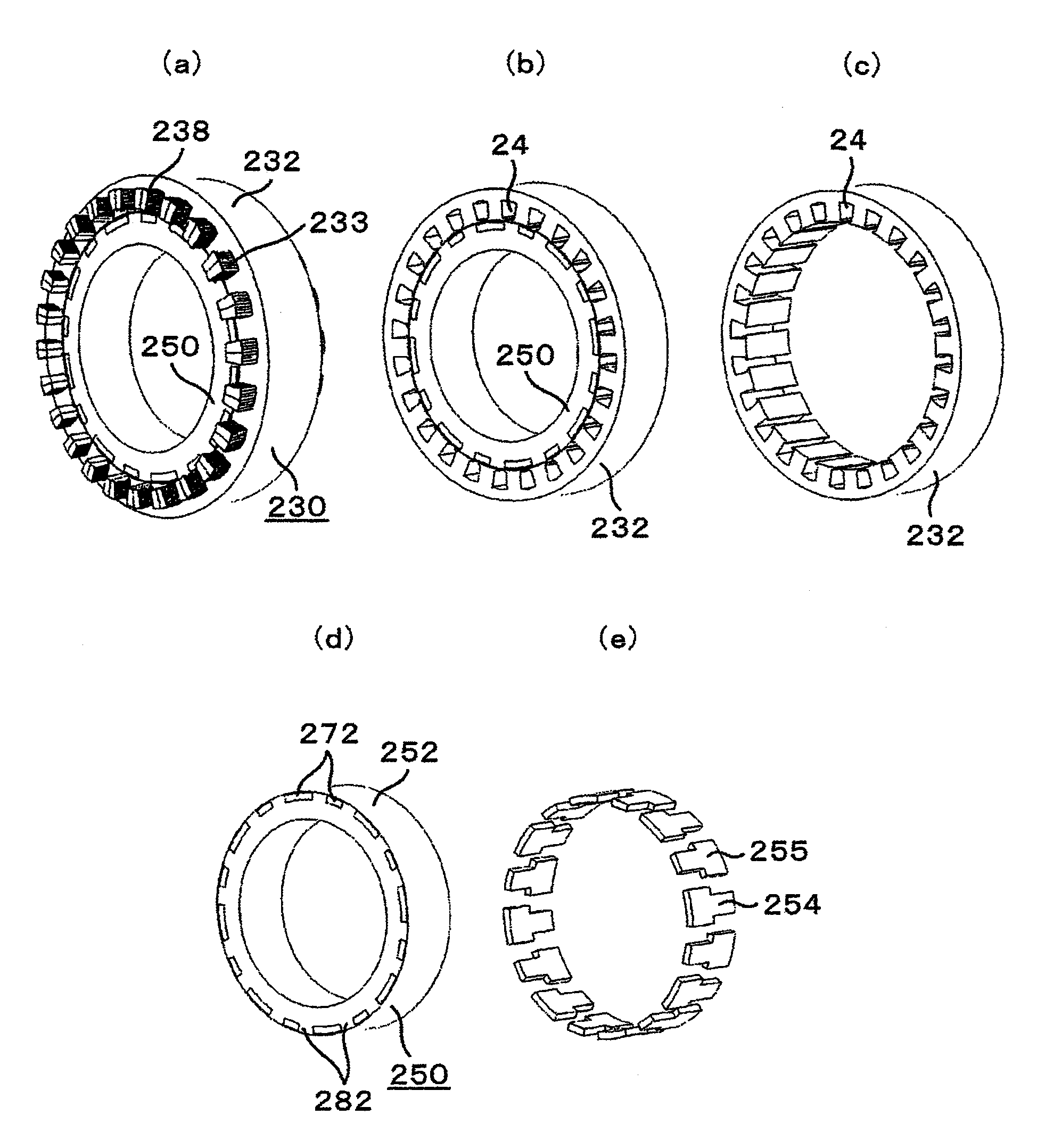
A rotating electric machine for vehicular use includes: a stator that includes a stator core and a stator winding wound at the stator core; and a rotor that is rotatably disposed relative to the stator and includes a rotor core formed by laminating a plurality of electromagnetic steel sheets with a plurality of magnet insertion holes formed therein and includes a plurality of permanent magnets each held in each of the plurality of magnet insertion holes to form a magnetic pole. Each of the plurality of permanent magnets extends along a rotor axis and is formed in a shape assuming at least two different lengths along a circumference of the rotor.

Description

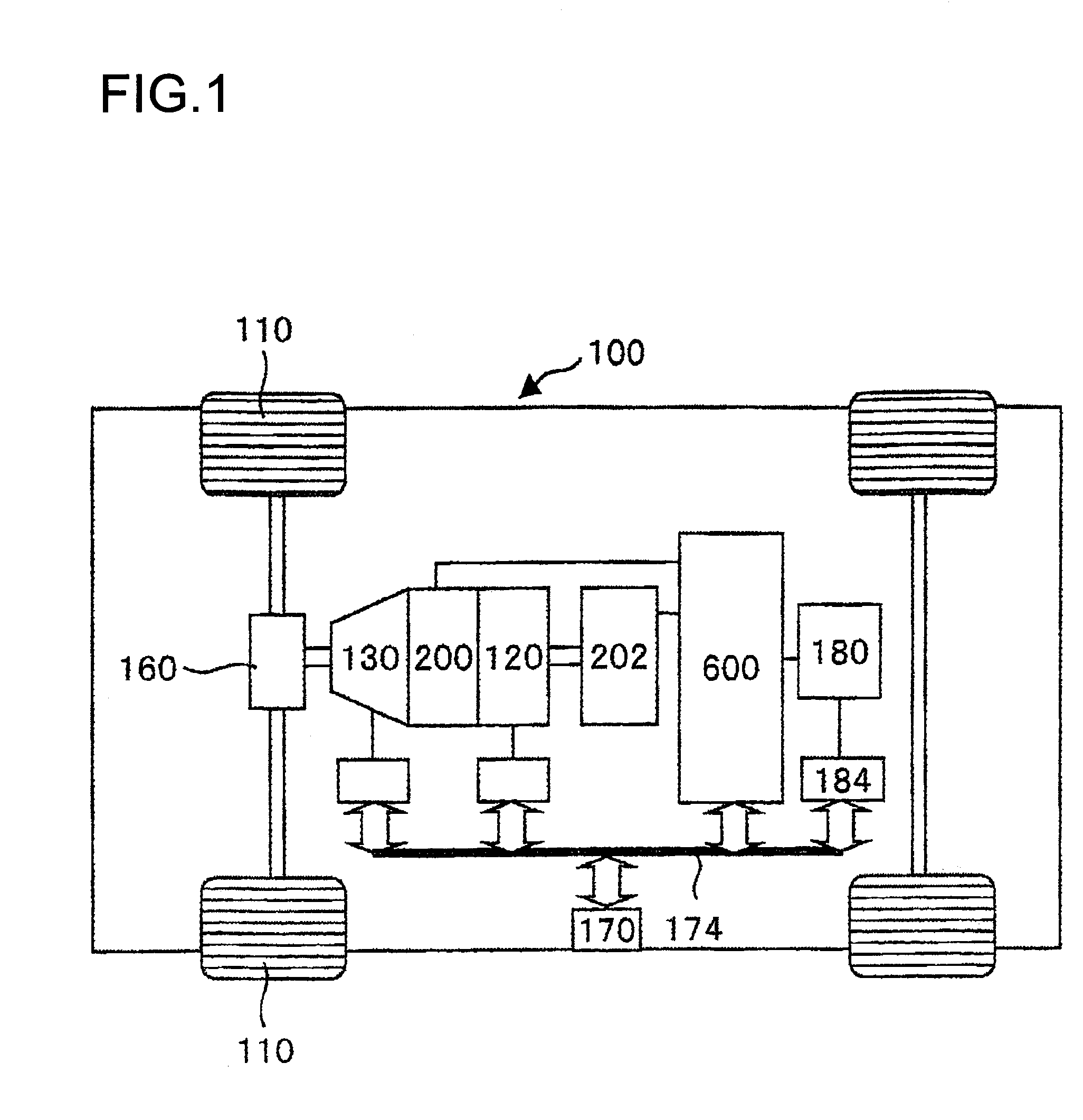
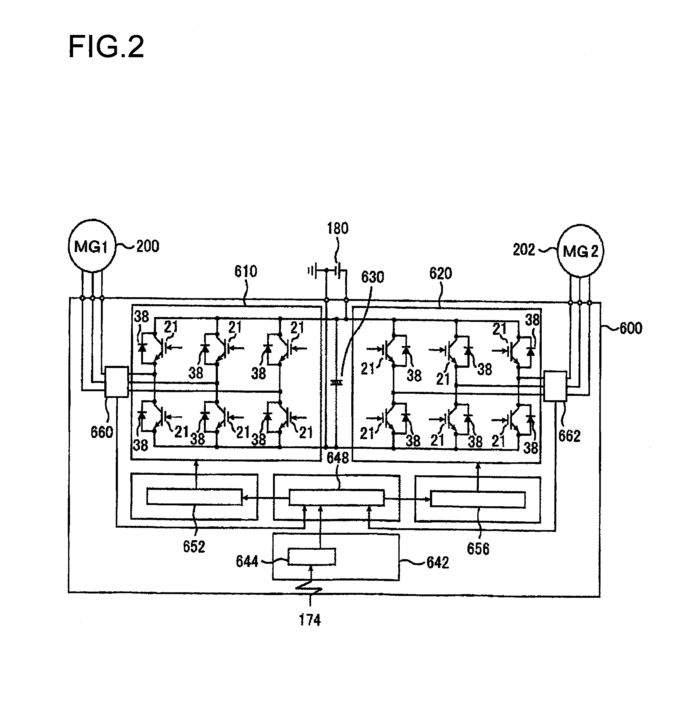
TECHNICAL FIELD[0001]The present invention relates to a rotating electric machine for vehicular use.BACKGROUND ART[0002]Steady efforts have been focused on the development of hybrid vehicles that travel based upon the outputs from both an engine and a rotating electric machine and pure electric vehicles that travel exclusively based upon the output torque provided by a rotating electric machine. In this specification, the term “electric vehicle” is used to refer to both a hybrid vehicle and a pure electric vehicle. The rotating electric machine installed in an electric vehicle to enable traveling operation, which is required to provide a large output, includes permanent magnets constituted with sintered rare-earth magnets having strong magnetic energy. In the rotating electric machine installed in the electric vehicle to propel the electric vehicle, the permanent magnets are embedded within a rotor core.[0003]Torque pulsations, induced by a cogging torque or the like, are bound to o...

Claims


Application Information

Patent Timeline
Patent Type & Authority Applications(United States)
IPC IPC(8): H02K21/12B60L50/15B60L50/16
CPCH02K1/276B60L2270/145H02K29/03H02K2201/06B60L1/02B60L3/0061B60L7/14B60L7/18B60L11/123B60L11/14B60L15/007B60L15/20B60L15/2009B60L2210/40B60L2240/12B60L2240/36B60L2240/421B60L2240/423H02K7/006B60L50/16B60L50/61Y02T10/62Y02T10/64Y02T10/70Y02T10/7072Y02T10/72
Inventor HINO, NORIAKIMATSUNOBU, YOTAKASUGIMOTO, SHINJIKAMIYA, AKINORISAITO, YASUYUKI
Owner HITACHI ASTEMO LTD
Learn More