Electrolytic process apparatus

a technology of electrolysis process and electrolysis chamber, which is applied in the direction of electrolysis apparatus, electrical-based machining apparatus, machining electric circuits, etc., can solve the problems of increasing the cost associated with plating the cathode, the inability to obtain a uniform thickness of deposited material on the cathode, and the inability to justify the cost of producing a conforming anode. , to achieve the effect of improving the electrolytic process

Inactive Publication Date: 2012-07-12
AUTOMATION SOLUTIONS
View PDF4 Cites 3 Cited by
  • Summary
  • Abstract
  • Description
  • Claims
  • Application Information

AI Technical Summary

Benefits of technology

[0019]Thus, by spacing the guard from the anode, in some embodiments a greater quantity of the electrolyte solution will be in contact with electrode, which may improve the electrolytic process compared with if the guard were directly in contact with a part of the electrode.

Problems solved by technology

A known problem with electro deposition is that it can be difficult to obtain a uniform thickness of deposited material on the cathode.
For example, if the cathode contains bores or relief profiles, it is possible that a fixed position anode may not cause the inside of the bore, for example, to be plated to a desirable thickness, uniformity or quality.
However, if the cathode is, for example, a one-off or rarely produced object, the cost of producing a conforming anode may not be justified.
Also, the cost and time involved with either using multiple anodes or moving a single anode to different positions with respect to the cathode increases the cost associated with plating the cathode.
A problem with using an auxiliary anode is that, should the anode touch the cathode, a spark or sparks may jump between the anode and cathode, which can burn the cathode.
In some cases, the burn caused by arcing occurring between the anode and cathode can structurally compromise the cathode.
For example, should the cathode be an aeroplane landing gear, which is purposefully made from thin and lightweight materials to keep the weight of the landing gear to a minimum, such a burn due to arcing could render the landing gear unusable.
Therefore, a single instance of contact between the anode and cathode has the potential to destroy an expensive object, such as a landing gear, that forms the cathode.
Whilst the insulating guard stops the anode from contacting the cathode, after time, the guard may wear and therefore permit the anode to touch the cathode, thereby permitting arcing to occur which can damage the cathode.

Method used


Image

  • Electrolytic process apparatus
  • Electrolytic process apparatus
  • Electrolytic process apparatus

Examples


Embodiment Construction

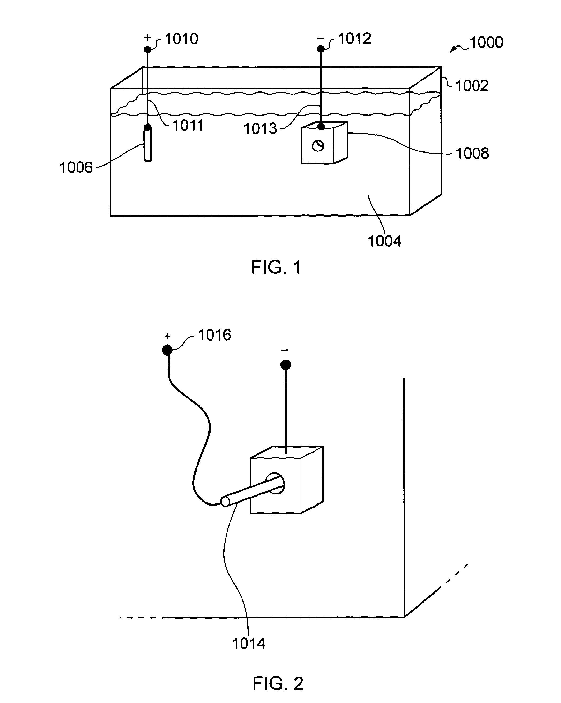
[0033]The following description relates to plating applications (where the work is connected to the negative terminal of the power supply). However, it is to be understood that the apparatus can be used in a wide range of electrolytic processes such as Plating, Anodising, Etching, Electro cleaning, Electro polishing, Electrophoretic painting, Electro colour, etc . . .

[0034]“The Work” (the part to be treated) can be either negative (in the case of plating applications) or positive in the case of anodising or as required by the particular process. In the case of some applications, such as electro colour, a mixture of AC & DC can also be used.

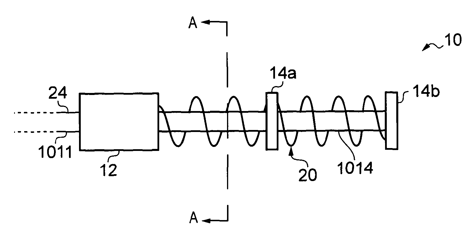
[0035]Referring to FIG. 4 a guarded auxiliary anode 10 is shown according to an embodiment of the invention. The guarded auxiliary anode 10 includes an anode 1014 arranged to be electrically coupled to the positive terminal 1010 of a direct current (DC) power supply, such as a rectifier, via an electrically insulated connecting wire 1011. Suitable...


PUM

PropertyMeasurementUnit
voltagesaaaaaaaaaa
voltageaaaaaaaaaa
currentaaaaaaaaaa

Abstract

Electrolytic process apparatus comprises a voltage source for electrically coupling to first and second electrodes, a detection circuit electrically coupled to the voltage source and a guard for providing a barrier between the first and second electrodes. The guard is arranged to permit current to travel within an electrolyte between the electrodes. The guard includes a guard conductor arranged to be electrically isolated from the electrodes. The guard conductor is arranged to be electrically coupled to the detection circuit such that the detection circuit can detect the presence of a current path between the guard conductor on the one hand and either electrode on the other hand.

Description

BACKGROUND[0001]1. Field[0002]The present invention relates to electrolytic process apparatus. The present invention also relates to a guard for providing a barrier between first and second electrodes in an electrolytic process apparatus and to a guarded electrode for electrolytic process apparatus.[0003]2. Background of the Invention[0004]Electro deposition is a known electrolytic process for depositing a layer of material, such as a metal, to a target surface. According to one known technique, as shown in FIG. 1, an electro deposition apparatus 1000 includes a tank 1002 containing an electrolyte solution 1004. A target object 1008 is connected to a negative terminal 1012 of a power supply (not shown) thus forming a cathode. A source object 1006 is connected to a positive terminal 1010 of the power supply, thus forming an anode. Both the anode 1006 and cathode 1008 are immersed in the electrolyte solution 1004. The power supply supplies a direct current (dc) to the anode 1006, ther...

Claims


Application Information

Patent Timeline
Patent Type & Authority Applications(United States)
IPC IPC(8): C25D21/12C25D17/00
CPCC25D17/10C25D17/008C25D21/12
Inventor BUTTACI, VINCENZO
Owner AUTOMATION SOLUTIONS
Why Eureka
Try Eureka