
Teat application device

a technology of application device and teat, which is applied in the field of teat application device, can solve the problems of teat treatment liquid to spurt in an uncontrolled jet from the outlet, and is likely to shoot, and achieve the effect of easy removal

Inactive Publication Date: 2012-07-12
AMBIC EQUIP
View PDF13 Cites 3 Cited by
  • Summary
  • Abstract
  • Description
  • Claims
  • Application Information

AI Technical Summary

Benefits of technology

[0014]Ensuring that the cross-sectional area of the outlet is greater than the horizontal cross-sectional area of the fluid supply conduit not only enables the treatment liquid to be dispensed into the cup portion at a faster rate, it also prevents the build up of back pressure within the fluid supply conduit. This back pressure has the tendency to cause the treatment liquid to spurt in an uncontrolled jet from the outlet and be likely to shoot out of the upper open first end of the cup portion. Thus the provision of an outlet with a cross-sectional area greater than the horizontal cross-sectional area of the fluid supply conduit is a key feature for improving the speed and efficiency that the cup portion can be replenished, and this benefit is obtained for a wide range of viscosities of treatment liquid, for example treatment liquids that range from non-viscous to substantially thicker than water and / or thixotropic.
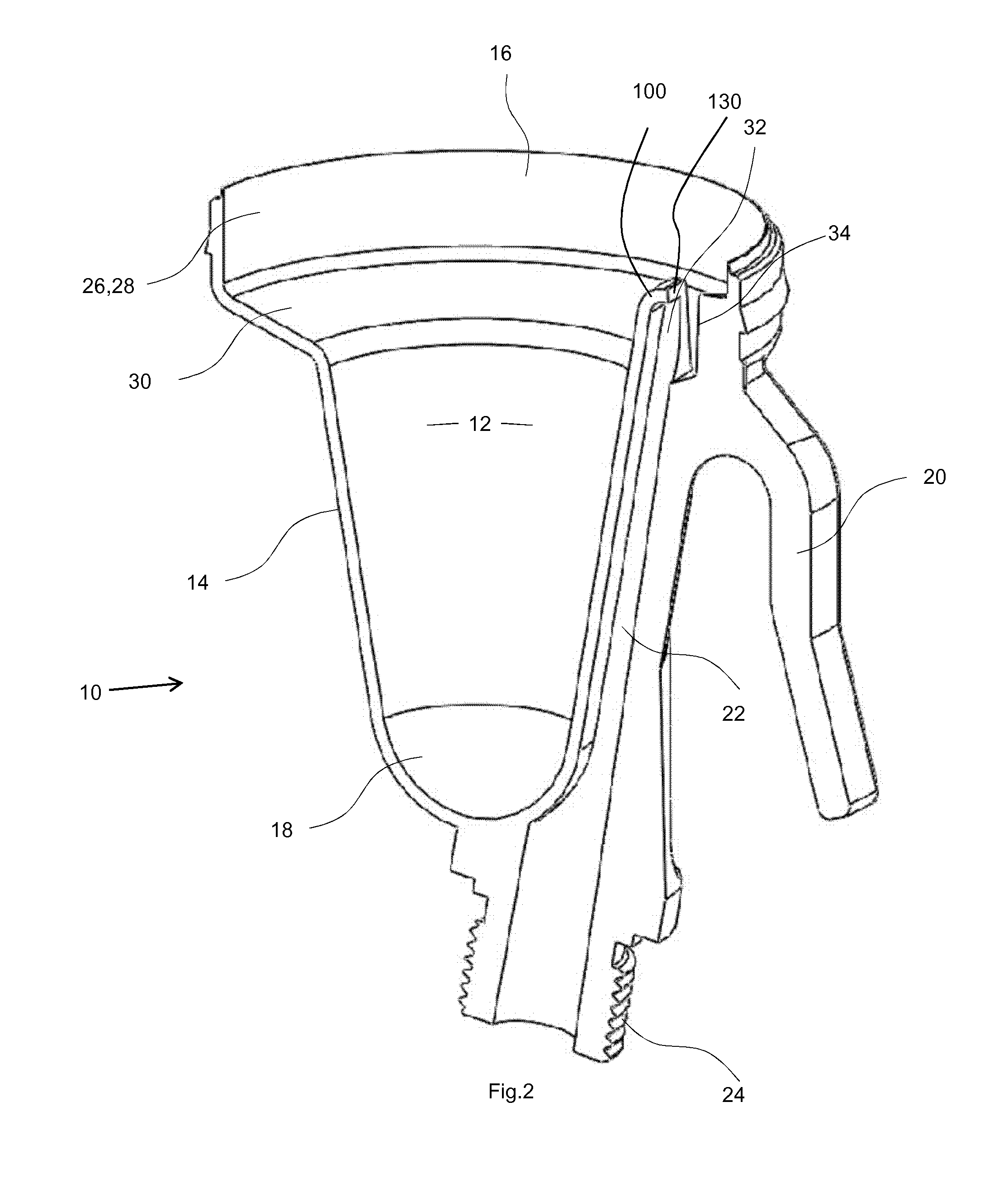
[0024]The present invention also provides the advantage that contaminated or otherwise unwanted liquid can easily be removed from the cup portion, without the need for dismantling the application device first. To achieve this, the application device of the present invention is simply turned over to orient the cup portion upside down and the unwanted liquid is tipped out of the upper open first end of the cup portion.

Problems solved by technology

This back pressure has the tendency to cause the treatment liquid to spurt in an uncontrolled jet from the outlet and be likely to shoot out of the upper open first end of the cup portion.
As described above, there are a number of problems associated with the use of separate fluid flow tubes in the application devices currently available.

Method used


Image

  • Teat application device
  • Teat application device
  • Teat application device

Examples


Embodiment Construction

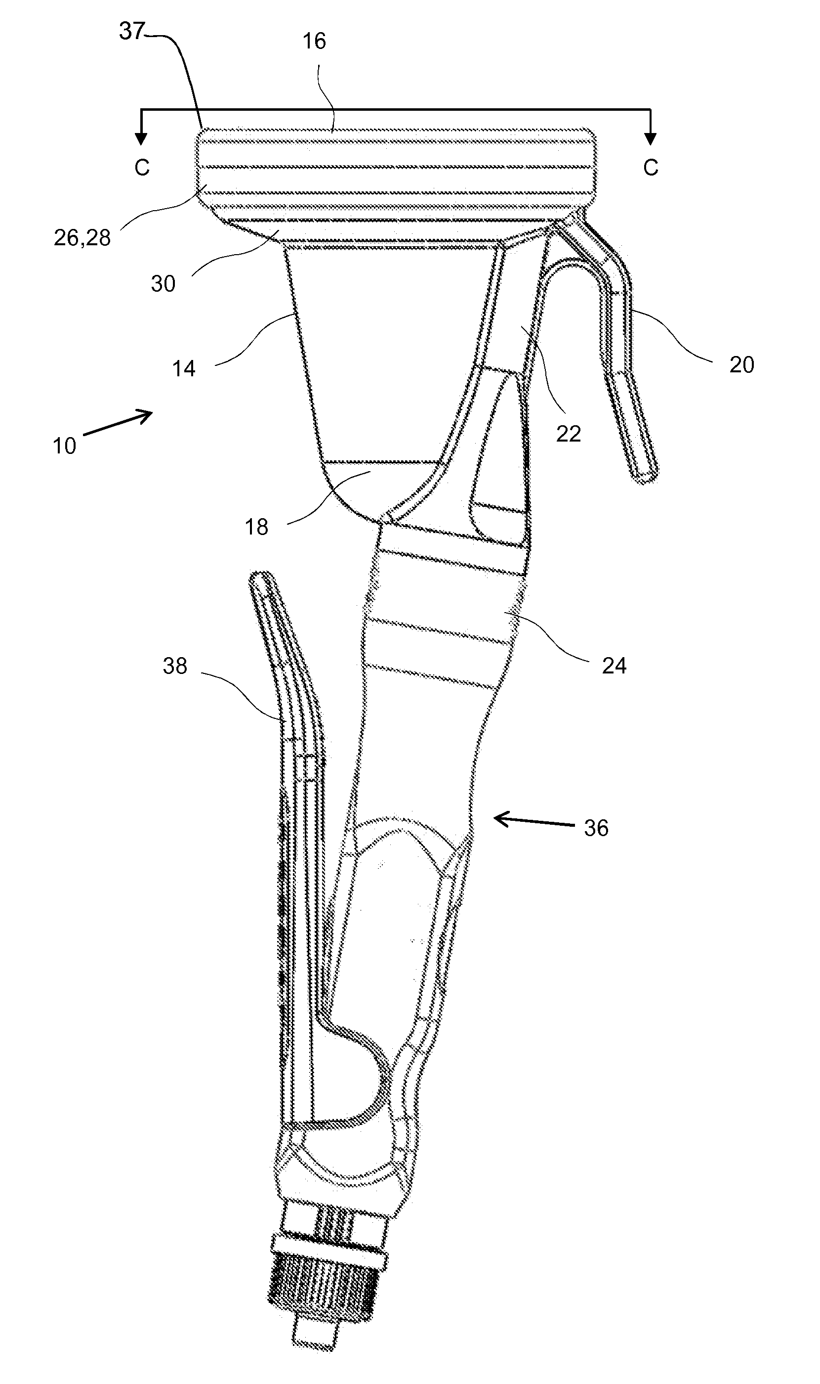
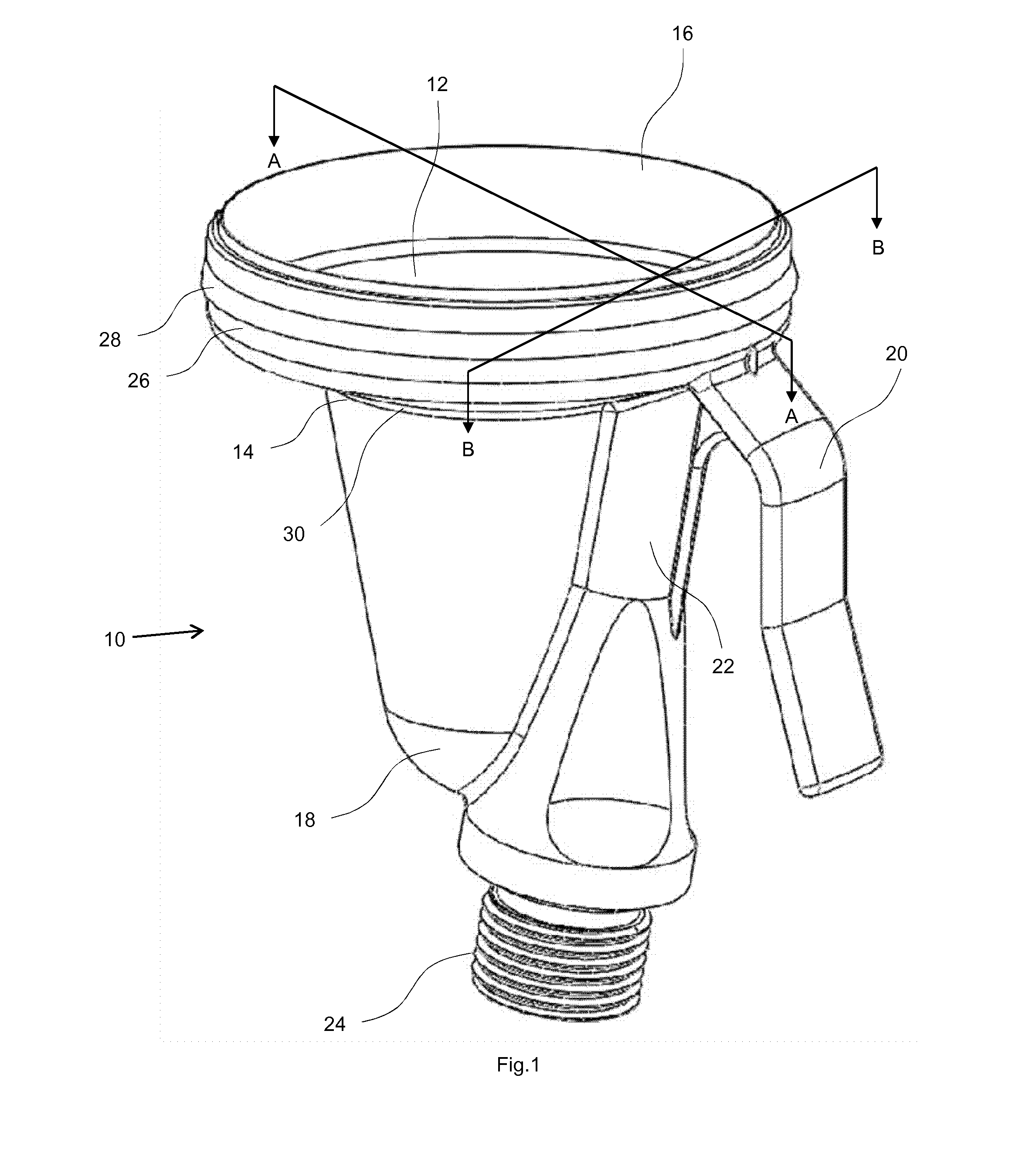
[0041]FIG. 1 shows a cup portion 10 used in an application device according to the present invention that is generally cylindrical in shape and has internal 12 and external 14 surfaces, an upper open first end 16 and a lower closed second end 18. The surfaces 12 and 14 taper inwards towards the lower closed second end 18. A hook 20 is attached towards the upper open first end 16 and on the external surface 14 of the cup portion 10. A fluid supply conduit 22 is formed on and in part defined by the external surface 14; this latter feature is more clearly illustrated by FIG. 2. The cup portion 10 may also be attached to either a container or a wand or lance, depending upon whether a container or a remote reservoir is being used, via a screw thread connection 24 provided in the fluid supply conduit 22. (As mentioned above, the screw thread connector may be replaced by a bayonet type or any other suitable type of fitting). The cup portion 10 has a full circumferential extension 26 that f...


PUM


Abstract

The present invention relates to an application device for treating the teats of milk producing animals with a liquid. The device comprises a dip cup with a fluid supply conduit having an outlet through which liquid is conveyed, wherein the cross-sectional sectional area of the outlet is larger than the cross-sectional area of fluid supply conduit. In a further embodiment, a baffle is provided to deflect the treatment liquid is a desired direction around the inside of the cup. In a still further embodiment the invention a fluid supply conduit is defined at least in part by the external wall of the dip cup.

Description

FIELD OF THE INVENTION[0001]The present invention relates to an application device for treating the teats of milk producing animals with a liquid. Typical milk producing animals that can be treated in this way are cows, sheep, buffalo and goats.BACKGROUND OF THE INVENTION[0002]In order to maintain the health and welfare of milk producing animals, as well as the quality of their milk, it is very important that their udders and teats are kept clean and healthy. In particular, the bacteria that cause mastitis infections must not be allowed to proliferate and contaminate the milk harvesting equipment, thus risking the transfer of pathogens from animal to animal. To guard against this problem it is well known to treat the teats of animals with a liquid, such as a liquid disinfectant or a washing solution, either immediately before and / or immediately after milking. In the case of a pre-milking treatment application the aim is primarily to remove foreign matter and kill the bacteria presen...

Claims


Application Information

Patent Timeline
IPC IPC(8): A01J7/04
CPCA61D11/00A01J7/04A61D7/00
Inventor HILEY, RICHARD JAMES
Owner AMBIC EQUIP
Learn More