
Method for reporting srs in discontinuous reception and wireless communication system thereof

Inactive Publication Date: 2012-07-05
SUNPLUS TECH CO LTD
View PDF4 Cites 128 Cited by
  • Summary
  • Abstract
  • Description
  • Claims
  • Application Information

AI Technical Summary

Benefits of technology

[0008]It is therefore a first objective of the present invention to provide a wireless communication system, so that the eNB can obtain instantaneous channel condition.
[0009]It is therefore a second objective of the present invention to provide a method for reporting SRS in discontinuous reception for accurate channel estimation, so that the radio resource can be allocated appropriately.
[0016]In the present invention, since the aperiodic SRS is reported by the UE both in active time and non-active time, the base station can obtain instantaneous channel condition information. Also, the network can allocate the radio resource accordingly.

Problems solved by technology

In a wireless communication system, how to efficiently distribute / allocate uplink transmission resources between multiple user equipments (UEs) is always a critical issue from the system point of view.

Method used


Image

  • Method for reporting srs in discontinuous reception and wireless communication system thereof
  • Method for reporting srs in discontinuous reception and wireless communication system thereof
  • Method for reporting srs in discontinuous reception and wireless communication system thereof

Examples


first embodiment

The First Embodiment

[0037]In the disclosure, a wireless communication system will be described, and an operation of the wireless communication system may be performed in a base station and a mobile station (MS) to administer the network and transmit data, system information, control signals, etc. For conveniently describing the present invention, the 3GPP LTE system is taken as an example in the following first embodiment, however, the wireless communication system provided in the present invention is not limited thereto. The base station may be served as eNode B (eNB), and the mobile station (MS) includes at least a UE.

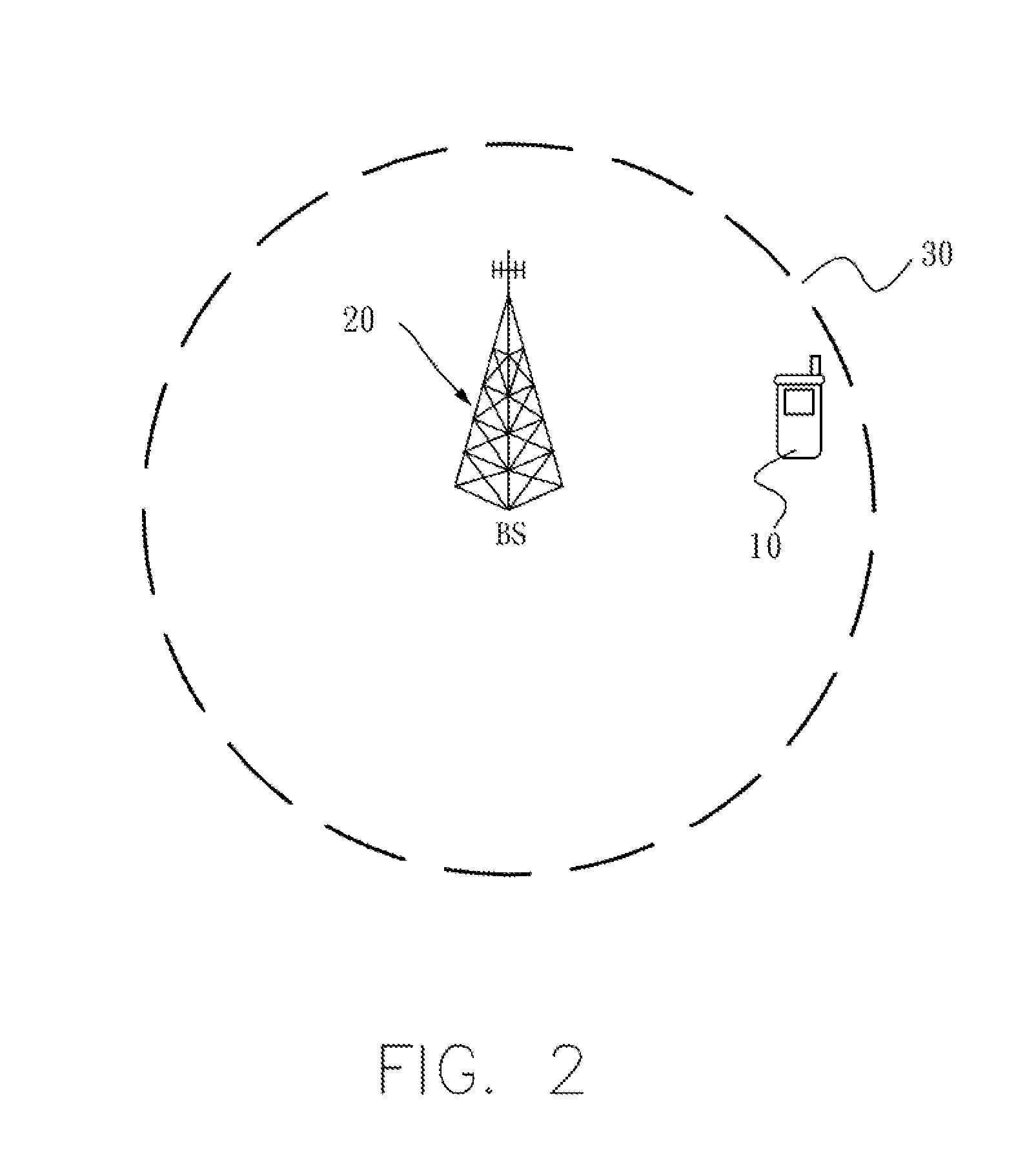
[0038]FIG. 2 illustrates a schematic diagram of a wireless communication system according to an embodiment of the present invention. Referring to FIG. 2, the wireless communication system is for example to include UE 10 and an eNB 20. Periodic or aperiodic SRS transmission technology may be applied to the UE 10 and the eNB 20. The eNB serves the serving cell 30, and ...

second embodiment

The Second Embodiment

[0044]In the following embodiment, the wireless communication system is similar to the wireless communication system described in the abovementioned embodiment. Therefore, the same part would be omitted in the second embodiment. Since the abovementioned embodiment already provided the periodic SRS transmission mechanism, the description of the periodic SRS transmission mechanism would be also omitted in the second embodiment.

[0045]In order to increase the transfer rate, technology for extending the bandwidth which has been developed, and a unit carrier that may be owned by a communication UE for such bandwidth extension is called a CC (component carrier). Accordingly, a scheme for aggregating multiple CCs is disclosed.

[0046]In other words, a plurality of conventional CCs may be aggregated and used. For example, 5 CCs may be aggregated and extended to produce a bandwidth having a maximum of 100 MHz. Technology for aggregating a plurality of CCs as described above...

third embodiment

The Third Embodiment

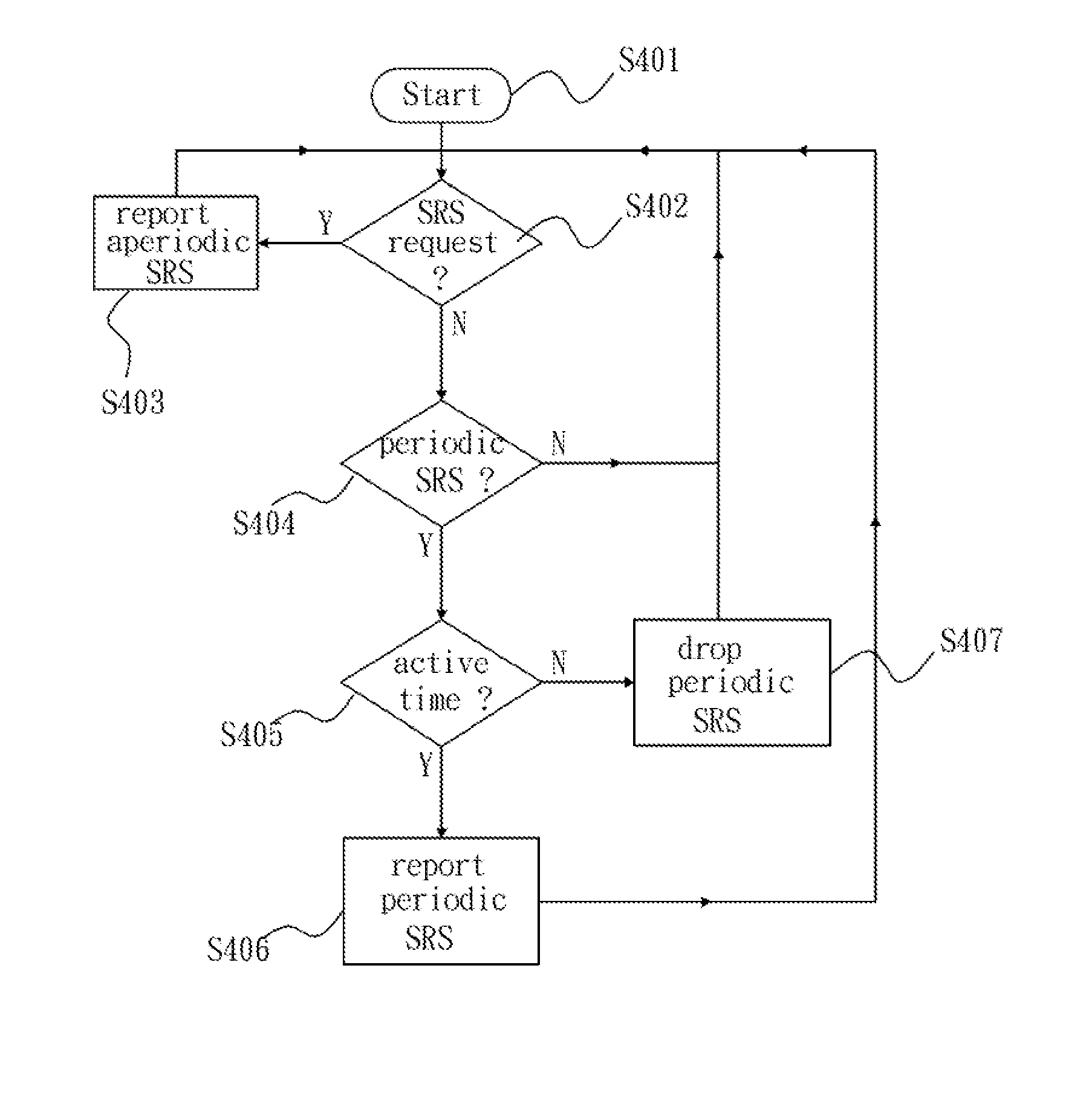
[0054]One method for reporting SRS in discontinuous reception can be summarized in accordance with the first embodiment shown in FIG. 4. FIG. 4 illustrates a flowchart depicting the method for reporting SRS in discontinuous reception according to third embodiment of the present invention. Referring to FIG. 4, the method includes the steps of:

[0055]In step S401, the method starts.

[0056]In step S402, it is determined whether a SRS request is received or not. In the above-mentioned embodiment, the SRS request can be transmitted through the PDCCH with a DCI format. When the SRS request is received, go to step S403. When the SRS request is not received, go to step S404.

[0057]In step S403, a SRS is transmitted. When the step S403 is performed, go back to the step S402. If the UE is in a non-active time, the transmitted SRS would be an aperiodic SRS.

[0058]In step S404, it is determined whether the periodic SRS is needed to be transmitted. If the periodic SRS is needed t...


PUM


Abstract

This invention relates to a method for reporting SRS in discontinuous reception and a wireless communication system thereof. The wireless communication system includes a user equipment (UE), a serving cell and a base station. The UE is for transmitting a periodic Sounding Reference Signal (SRS) and an aperiodic SRS, wherein the UE monitors a PDCCH in an active time. The serving cell has a serving range, wherein the UE is in the serving range of the serving cell. The base station is for performing connection to the UE and serving the serving cell. The UE transmits the aperiodic SRS no matter whether UE is in active time or not when the UE has been triggered to report the aperiodic SRS by a SRS request from the base station.

Description

[0001]This application claims the benefit of U.S. Provisional Application No. 61 / 429,584 filed on Jan. 4, 2011, the content of which is hereby incorporated by reference.BACKGROUND OF THE INVENTION[0002]1. Field of Invention[0003]The present invention relates in general to a Sounding Reference Signal transmission, and more particularly to an aperiodic Sounding Reference Signal transmission during Discontinuous Reception in a wireless communication system.[0004]2. Related Art[0005]In a wireless communication system, how to efficiently distribute / allocate uplink transmission resources between multiple user equipments (UEs) is always a critical issue from the system point of view. In order to achieve better resource scheduling, some mechanisms which is used for enabling UEs to provide related information to inform the network side of the quality of the channel, are usually introduced in the wireless communication system. For example, a Sounding Reference Signal (SRS) is introduced in th...

Claims


Application Information

Patent Timeline
IPC IPC(8): H04W52/02H04W4/00
CPCH04W76/048H04L5/006H04W76/28
Inventor ZHANG, YUANYUANLU, TSUNG-LIANG
Owner SUNPLUS TECH CO LTD
Learn More