Flexible Collet Anchor Assembly with Compressive Load Transfer Feature

a collet anchor and flexible technology, applied in the field of collet anchors, to achieve the effect of greater tensile load

Active Publication Date: 2012-07-05
BAKER HUGHES INC
View PDF27 Cites 3 Cited by
  • Summary
  • Abstract
  • Description
  • Claims
  • Application Information

AI Technical Summary

Problems solved by technology

One of the issues with this design in tensile loading with pressure differential coming from above is that the stress is transmitted through the window structure and the thin segments of the housing that defines the region between the windows so that the stress on the housing can get to the dogs that are extended into the recess of the landing nipple in the tubing string.

Method used


Image

  • Flexible Collet Anchor Assembly with Compressive Load Transfer Feature
  • Flexible Collet Anchor Assembly with Compressive Load Transfer Feature

Examples


Embodiment Construction

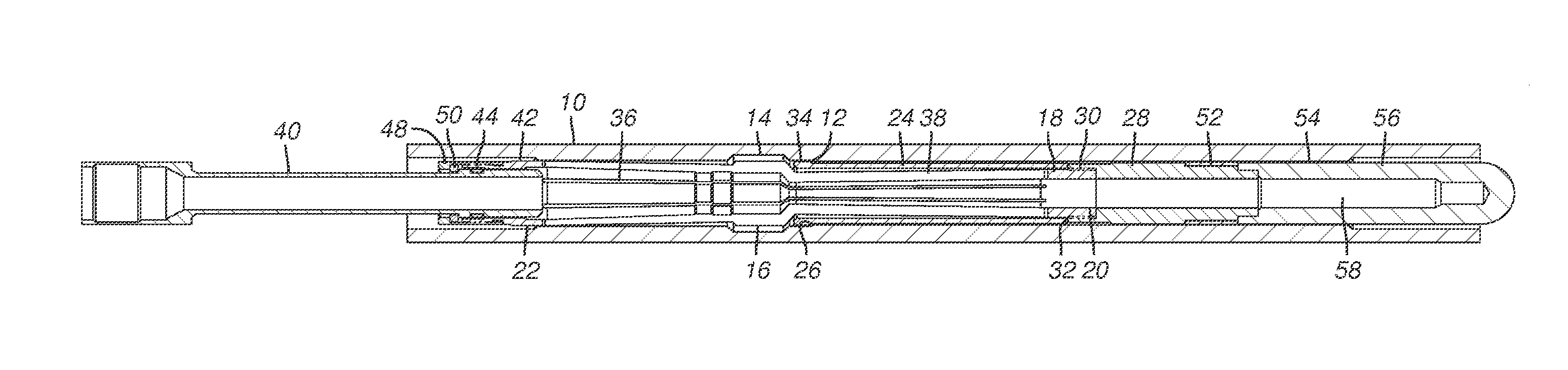
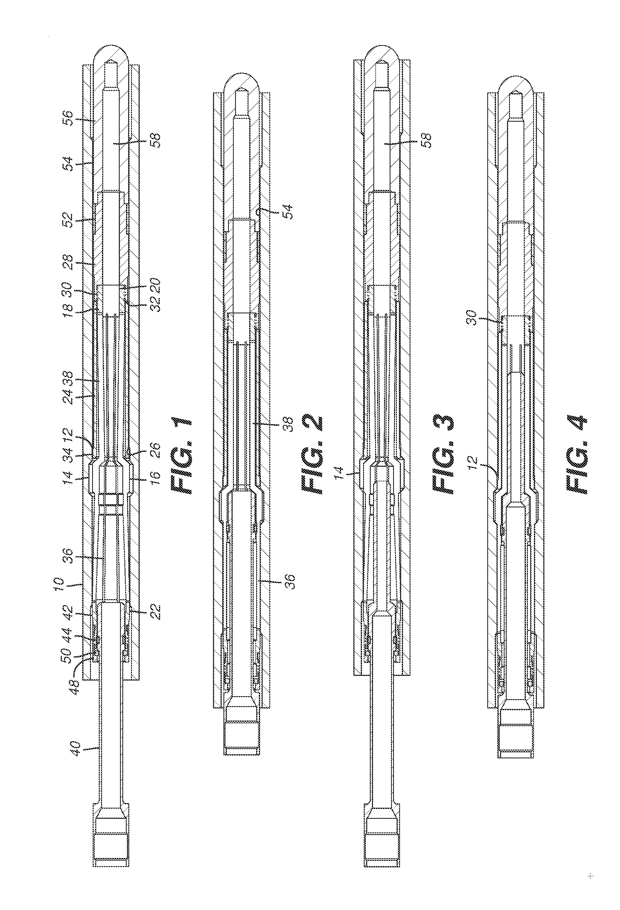
[0011]Referring to FIG. 1 a tubular string or a landing collar in a tubular string is represented as 10. It has a landing shoulder 12 and recess 14 a little above the shoulder 12. Recess 14 can be a circumferential groove or a series of adjacent groove segments that accept the collet heads 16 as shown in the set position of FIG. 2. Housing 18 has a lower end 20 and an upper end 22. The lower end 20 has a smaller outer dimension than the upper end 22 because a landing sleeve 24 with a generally radial surface 26 is disposed over the housing 18 between the collet heads 16 and the lower end 20. Lower end 20 supports a sleeve 28 at thread 30. Sleeve 28 defines a support surface 32 for landing sleeve 24. The upper end 34 of the landing sleeve 24 is designed to contact the collet heads 16 when they are extended into recess 14. This contact can occur when the collet heads 16 are initially extended into the recess 14, which lifts sleeve 24 off the shoulder 12, or it can happen after a diffe...


PUM


Abstract

A collet assembly has a housing and the collets disposed on flexible fingers connected to the housing at their opposed ends. A surrounding landing sleeve stops the assembly so that collets are aligned with a recess in a landing collar that is part of a surrounding tubing string. Once set the landing sleeve transmits compressive loads so that compressive stress essentially bypasses the finger structure supporting the collets. The fingers are initially tapered toward a longitudinal axis so that when internally supported they assume an aligned orientation to the housing axis to allow greater tensile loading and to provide a retraction force when the housing is to be removed after the collet support is removed.

Description

FIELD OF THE INVENTION[0001]The field of the invention is collet type anchors for subterranean use and more particularly the collets that are located on flexible fingers for engaging a profile in a tubular string and providing additional features to retain large loads that limit stress to the fingers that support the collet.BACKGROUND OF THE INVENTION[0002]Locking devices for support of tools such as plugs in a tubular string have been used in the past. These designs use a recess profile in the string as the location for the engagement of the lock device that supports the tool such as a plug. Typically the string has a no go shoulder so that when the assembly is introduced into the string and hits a travel limit there are an assembly of dogs that are selectively extendable through windows in the housing. These dogs are then extended radially by a sleeve within the tool that has an exterior ramp that engages the dogs. As the sleeve advances the dogs are cammed out and the sleeve has ...

Claims


Application Information

Patent Timeline
Patent Type & Authority Applications(United States)
IPC IPC(8): E21B40/00
CPCE21B23/02
Inventor AVANT, MARCUS A.MURRAY, DOUGLAS J.
Owner BAKER HUGHES INC
Why Eureka
Try Eureka