
Method for Selecting Sensor Nodes

a sensor node and sensor node technology, applied in the field of method for selecting sensor nodes, can solve the problems of not being able to facilitate people to recognize objects o′, the coverage problem must be considered, and the image captured by the three surveillance devices cannot achieve the effect of best efficiency

Active Publication Date: 2012-06-28
NATIONAL TSING HUA UNIVERSITY
View PDF8 Cites 2 Cited by
  • Summary
  • Abstract
  • Description
  • Claims
  • Application Information

AI Technical Summary

Benefits of technology

[0010]The primary objective of the present invention is to provide a method for selecting sensor nodes, in which a coverage level of a plurality of objects made by a plurality of sensor nodes would be determined and a contribution function for the objects contributed by the sensor nodes would also be calculated, so that the sensor nodes having maximum contribution to the objects can be selected and arranged in a specific environment, and the sensing direction of those sensor nodes can be adjusted for making the sensor node group performs the best efficiency.
[0011]The another objective of the present invention is to provide a method for selecting sensor nodes, in which a sub sensor node group capable of sensing covering an object group would be arranged and the value of the contribution function for the objects contributed by the sensor nodes would also be calculated, such that the sensor nodes having maximum contribution to the objects can be selected and arranged in a specific environment, and the sensing direction of those sensor nodes can be adjusted for making the sensor node group performs the best efficiency.

Problems solved by technology

However, the wireless sensor network has a foundation problem that is coverage problem.
The coverage problem means a condition of a filed or an object that a sensor can monitor it; Moreover, with different monitoring environments, the wireless sensor network needs to deal with different coverage problems.
So that, when we want to deploy the wireless sensor network in a particular environment, the coverage problem must be considered in advance.
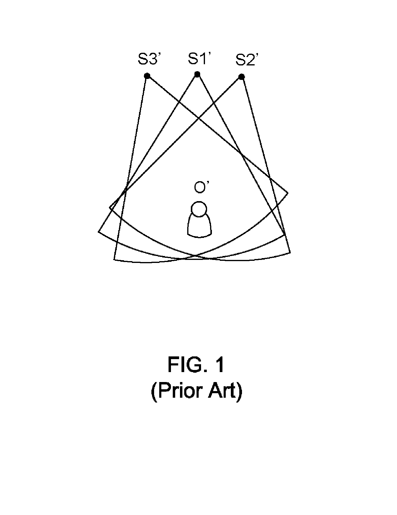
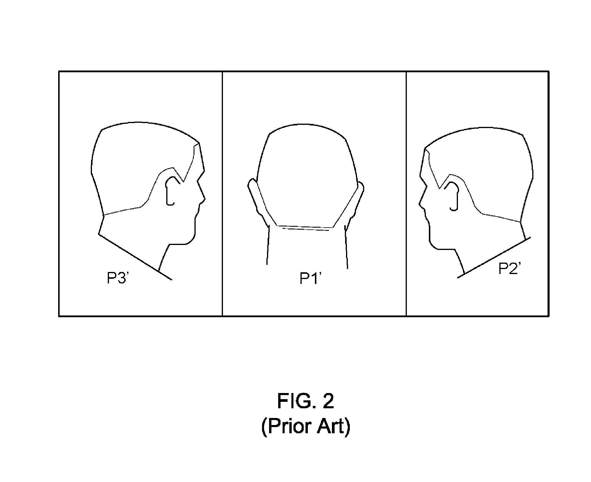
Obviously, The covering ranges of three surveillance devices S1′, S2′, and S3′ fully cover the object O′, however, the images captured by the three surveillance devices can not facilitate people recognize the identification of the object O′.

Method used


Image

  • Method for Selecting Sensor Nodes
  • Method for Selecting Sensor Nodes
  • Method for Selecting Sensor Nodes

Examples


Embodiment Construction

[0045]To more clearly describe a method for selecting sensor nodes according to the present invention, embodiments of the present invention will be described in detail with reference to the attached drawings hereinafter.

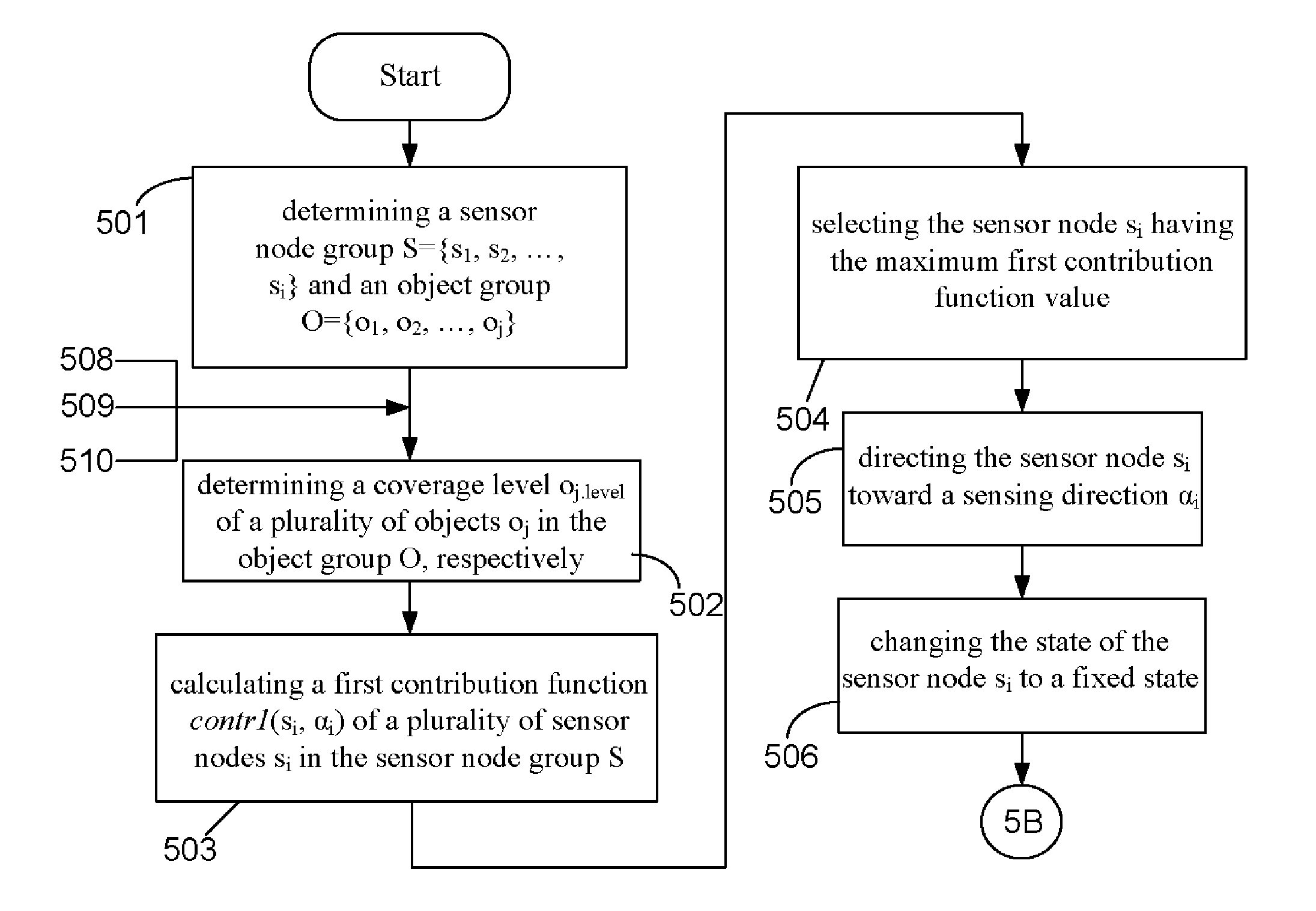
[0046]Please refer to FIG. 5A and FIG. 5B, which illustrate flow charts of a method for selecting sensor nodes according to the present invention. As shown in FIG. 5A and FIG. 5B, the method for selecting sensor nodes includes main steps of:

[0047]Firstly, executing step (501), determining a sensor node group S={s1, s2, . . . , si} and an object group O={o1, o2, oj}, and then executing step (502), determining a coverage level oj.level of a plurality of objects oj in the object group O, respectively. After the step (502) is finished, the flow is proceeded to step (503), calculating a first contribution function contr1 (si, αi) of a plurality of sensor nodes si in the sensor node group S; Next proceeding to step (504), selecting the sensor node si having the maximum fir...


PUM


Abstract

The present invention relates to a method for selecting sensor nodes, the method is adopted for calculating the value of a contribution function for a plurality of objects contributed by a plurality of sensor nodes, wherein the contribution function value is calculated by way of determining a coverage level of the objects made by the sensor nodes, or by means of arranging a sub sensor node group capable of sensing covering an object group and calculating the value of the contribution function for the objects contributed by the sensor nodes; Therefore, through the method, the sensor nodes having maximum contribution to the objects can be selected and arranged in a specific environment, and the sensing direction of those sensor nodes can be adjusted for making the sensor node group performs the best efficiency.

Description

BACKGROUND OF THE INVENTION[0001]1. Technical Field[0002]The present invention relates to a method for solving the coverage of sensor nodes, and more particularly, to a method for selecting sensor nodes, in which the sensor nodes having best sensing coverage can be selected by way of determining a coverage level of the objects made by the sensor nodes and calculating the value of a contribution function for the objects contributed by the sensor nodes[0003]2. Description of Related Art[0004]Wireless sensor network consists of a plurality of sensor nodes, in which, each sensor node is responsible for collecting, processing, and storing the environment data. Moreover, the sensor node can communicate with any adjacent sensor node. Since the sensor node of wireless sensor network has the above properties, it can be applied to many environmental sensing applications, such as video surveillance system, radiation sensing, and biochemistry sensing, etc.[0005]However, the wireless sensor netw...

Claims


Application Information

Patent Timeline
IPC IPC(8): G06F17/10
CPCG01B11/022H04N7/18G01D21/00H04L67/12G06K9/00771G06V20/52
Inventor CHEN, PO-YUTSENG, YU-CHEECHEN, WEN-TSUEN
Owner NATIONAL TSING HUA UNIVERSITY
Learn More