
Method of driving piezoelectric device

a piezoelectric device and piezoelectric technology, applied in piezoelectric/electrostrictive/magnetostrictive devices, piezoelectric/electrostriction/magnetostriction machines, electrical apparatus, etc., can solve the problem of steep change of piezoelectric characteristics, excessive bias electric field applied, and significant deviation from desired amount of displacemen

Inactive Publication Date: 2012-06-28
CANON KK
View PDF10 Cites 10 Cited by
  • Summary
  • Abstract
  • Description
  • Claims
  • Application Information

AI Technical Summary

Benefits of technology

[0014]In view of the above-mentioned problem, an object of the present invention is to provide a method of driving a piezoelectric device capable of using circuit elements having low withstand voltage by suppressing a steep decrease or inversion of polarization of the piezoelectric material by applying a minimal and necessary bias electric field, and of obtaining a desired displacement even if temperature changes.
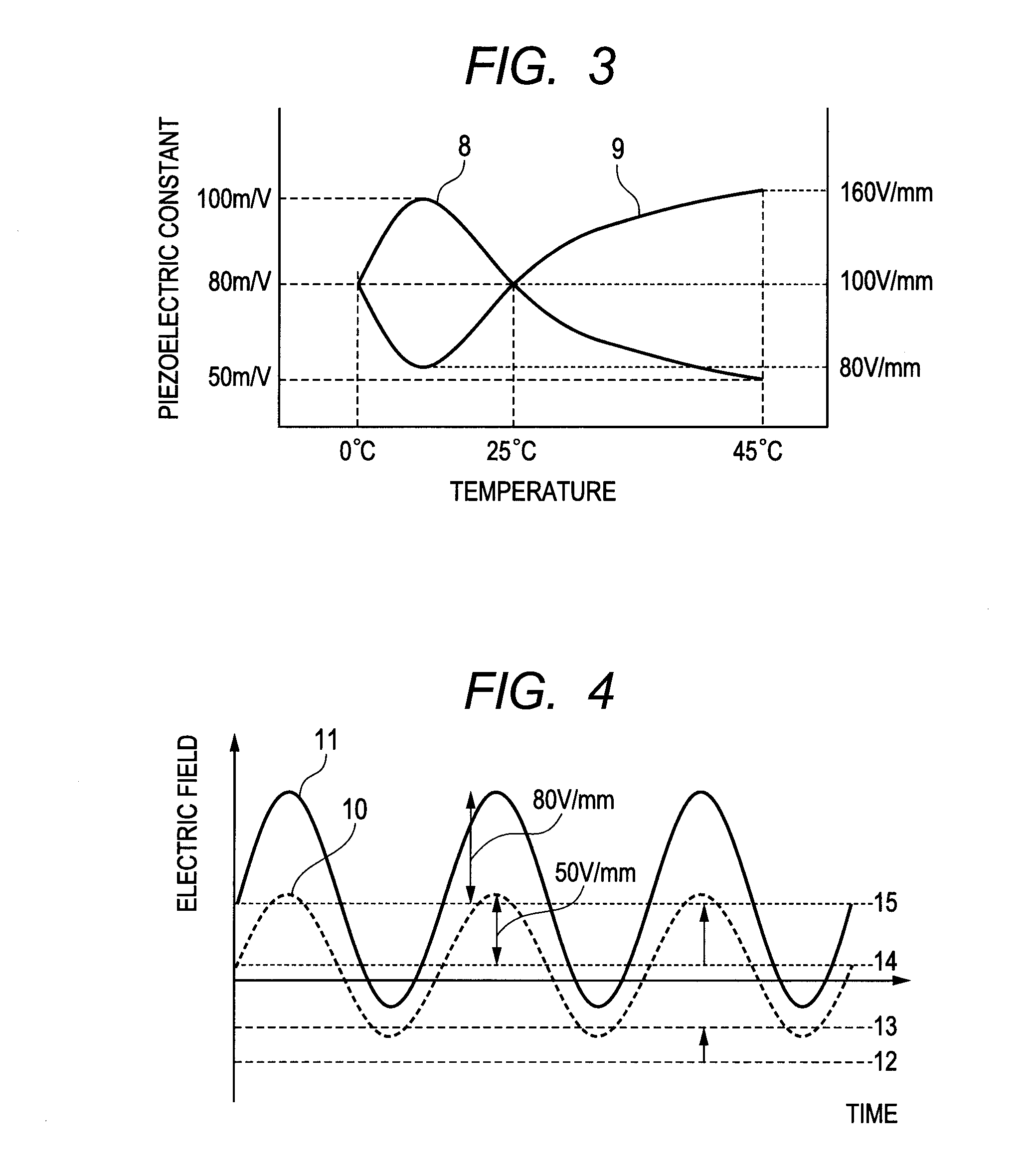
[0015]According to the present invention, there is provided a method of driving a piezoelectric device to generate oscillation in the piezoelectric device, the piezoelectric device including a piezoelectric material having at least two phase transition temperatures and is polarized in a thickness direction, and electrodes disposed on both end surfaces of the piezoelectric material in a direction orthogonal to the polarized direction, the method including: applying an alternating electric field to the piezoelectric device by electric field applying unit; and applying a bias electric field in accordance with a variation of a coercive electric field due to temperature variation so that an absolute value of an electric field in a direction opposite to the polarized direction in the alternating electric field applied by the electric field applying unit becomes smaller than the coercive electric field and so that a polarization of the piezoelectric material is not reversed by the electric field in the direction opposite to the polarized direction.
[0016]According to the present invention, it is possible to realize a method of driving a piezoelectric device capable of using circuit elements having low withstand voltage by suppressing a steep decrease or inversion of polarization of the piezoelectric material by applying a minimal and necessary bias electric field, and of obtaining a desired displacement even if temperature changes.

Problems solved by technology

Therefore, when a non-lead-based piezoelectric material such as barium titanate is used for a piezoelectric device, there is a problem in that a displacement becomes significantly deviated from a desired amount by a slight change of temperature at a temperature close to the phase transition temperature.
On the other hand, if a high bias electric field is set corresponding to the coercive electric field on the high temperature side, an excessive bias electric field is applied on a relatively low temperature in which the coercive electric field becomes relatively large.
In addition, there is a problem in that if the piezoelectric material has a phase transition temperature at temperature close to the room temperature, there is a steep change of piezoelectric characteristics due to phase transition, and hence a slight change of temperature causes a large deviation of a real displacement from a desired displacement.

Method used


Image

  • Method of driving piezoelectric device
  • Method of driving piezoelectric device
  • Method of driving piezoelectric device

Examples


example

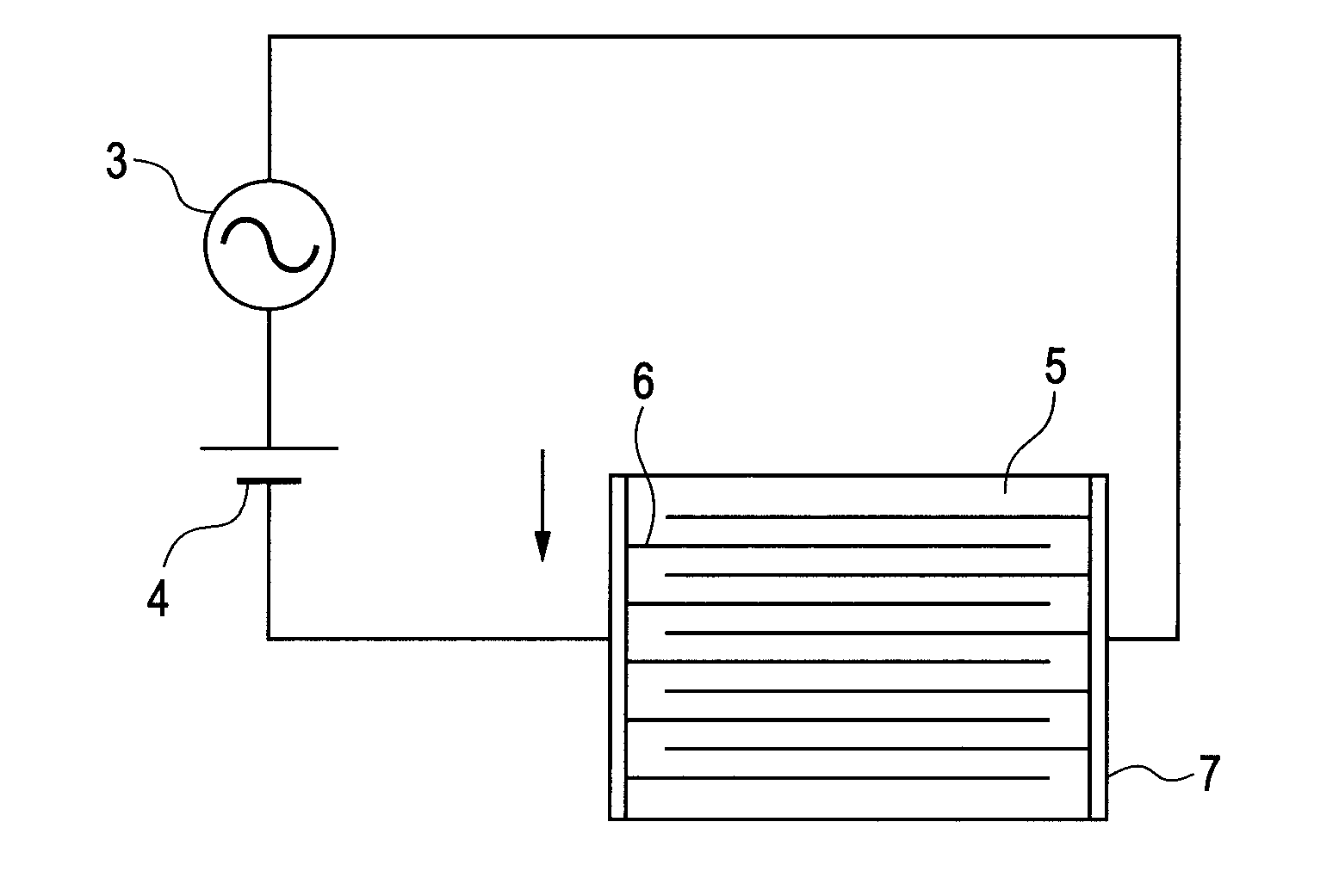
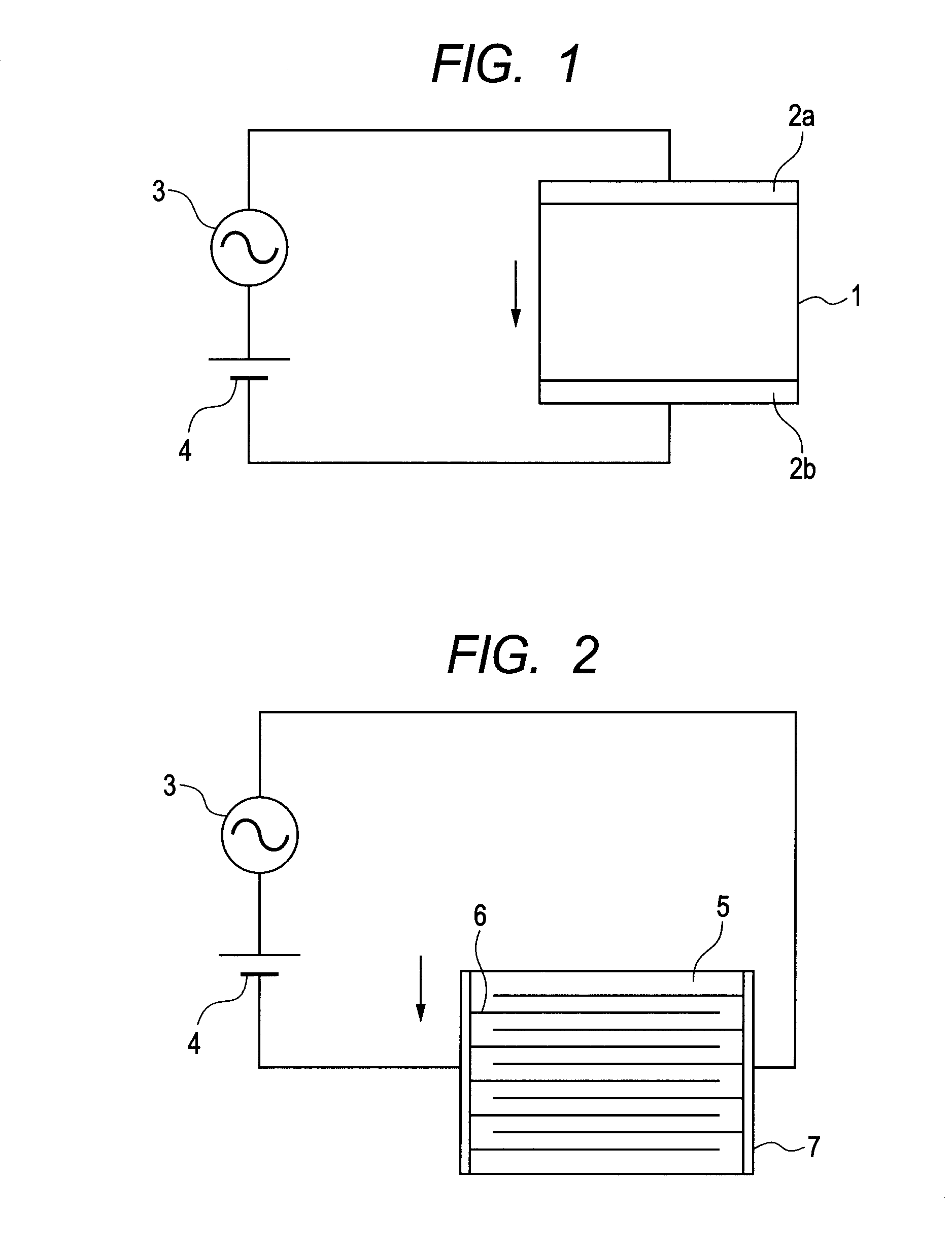
[0025]FIG. 1 is a diagram illustrating a method of driving a piezoelectric device including a piezoelectric material having two or more phase transition temperatures in an example of the present invention and is polarized in one of thickness directions, and electrodes disposed on both end surfaces of the piezoelectric material in a direction orthogonal to the polarized direction.

[0026]Then, the piezoelectric device of this example is constituted so as to generate oscillation when an alternating electric field is applied by electric field applying unit.

[0027]In addition, as illustrated in FIG. 1, a piezoelectric material 1 is polarized in an arrow direction of the diagram (in one of thickness directions).

[0028]In this example, the piezoelectric material 1 is a non-lead piezoelectric material that contains barium titanate as a main component but contains no lead.

[0029]In addition, electrodes 2a and 2b are disposed on both end surfaces in the direction perpendicular to this polarizatio...


PUM


Abstract

Provided is a method of driving a piezoelectric device including a piezoelectric material having at least two phase transition temperatures and is polarized in one of thickness directions, and electrodes disposed on both end surfaces of the piezoelectric material in a direction orthogonal to the polarized direction, the method including: applying an alternating electric field to the piezoelectric device by an electric field applying unit; and applying a bias electric field in accordance with a variation of a coercive electric field due to temperature variation so that an absolute value of an electric field in a direction opposite to the polarized direction in the alternating electric field applied by the electric field applying unit becomes smaller than the coercive electric field and so that a polarization of the piezoelectric material is not reversed by the electric field in the direction opposite to the polarized direction.

Description

BACKGROUND OF THE INVENTION[0001]1. Field of the Invention[0002]The present invention relates to a method of driving a piezoelectric device, and more particularly, to a method of driving a piezoelectric device that can be applied appropriately to an ultrasonic motor, a foreign substance removing apparatus (a dust removing apparatus), utilizing ultrasonic oscillation.[0003]2. Description of the Related Art[0004]Lead titanate zirconate has been mainly used as a piezoelectric material to be an oscillation excitation source of a piezoelectric actuator utilizing an oscillation displacement of an ultrasonic motor, a foreign substance removing apparatus (a dust removing apparatus), and the like.[0005]However, along with an increasing awareness of environment, development of a non-lead piezoelectric material that does not contain lead is in progress.[0006]One of such non-lead piezoelectric materials, there is a barium titanate-based material.[0007]Barium titanate has a relatively high piezo...

Claims


Application Information

Patent Timeline
Patent Type & Authority Applications(United States)
IPC IPC(8): H01L41/09H01L41/083H01L41/187H01L41/22H02N2/00
CPCH01L41/042H01L41/1873H01L41/1871H10N30/802H10N30/8536H10N30/8542
Inventor SHIMADA, AKIRAOHASHI, KAISHI
Owner CANON KK
Learn More