
Lubricating oil feeding structure of engine

a technology of lubricating oil and feeding structure, which is applied in the direction of lubricant mounting/connection, lubrication elements, pressure lubrication, etc., can solve the problems of difficult attachment and detachment of the oil cooler b>300/b>, and the difficulty of attachment and detachment of the oil filter b>403/b>

Active Publication Date: 2012-06-28
KAWASAKI MOTORS LTD
View PDF5 Cites 12 Cited by
  • Summary
  • Abstract
  • Description
  • Claims
  • Application Information

AI Technical Summary

Benefits of technology

"The present invention provides a lubricating oil feeding structure for an engine that can maintain oil cooling performance by avoiding thermal influence from exhaust pipes and easily attaching and detaching an oil cooler. The structure includes an oil pump, oil filter, and oil cooler arranged in a cover member covering the end of the crankcase in the crankshaft direction. The cover member can be a generator cover or a front cylinder of the engine. The oil cooler can be arranged in a space on the outer side in the radial direction of the rotor or in the front lower part of the front cylinder. The cover member can also have a water pump for feeding cooling water to the oil cooler. The invention simplifies the structure of the cooling water passage and reduces the number of parts and assembly tasks."

Problems solved by technology

Thus, attachment and detachment tasks of the oil cooler 300 are not easily performed.
Thus, the attachment and detachment tasks at the time of replacing the oil filter 403 are not easily performed.

Method used


Image

  • Lubricating oil feeding structure of engine
  • Lubricating oil feeding structure of engine
  • Lubricating oil feeding structure of engine

Examples


Embodiment Construction

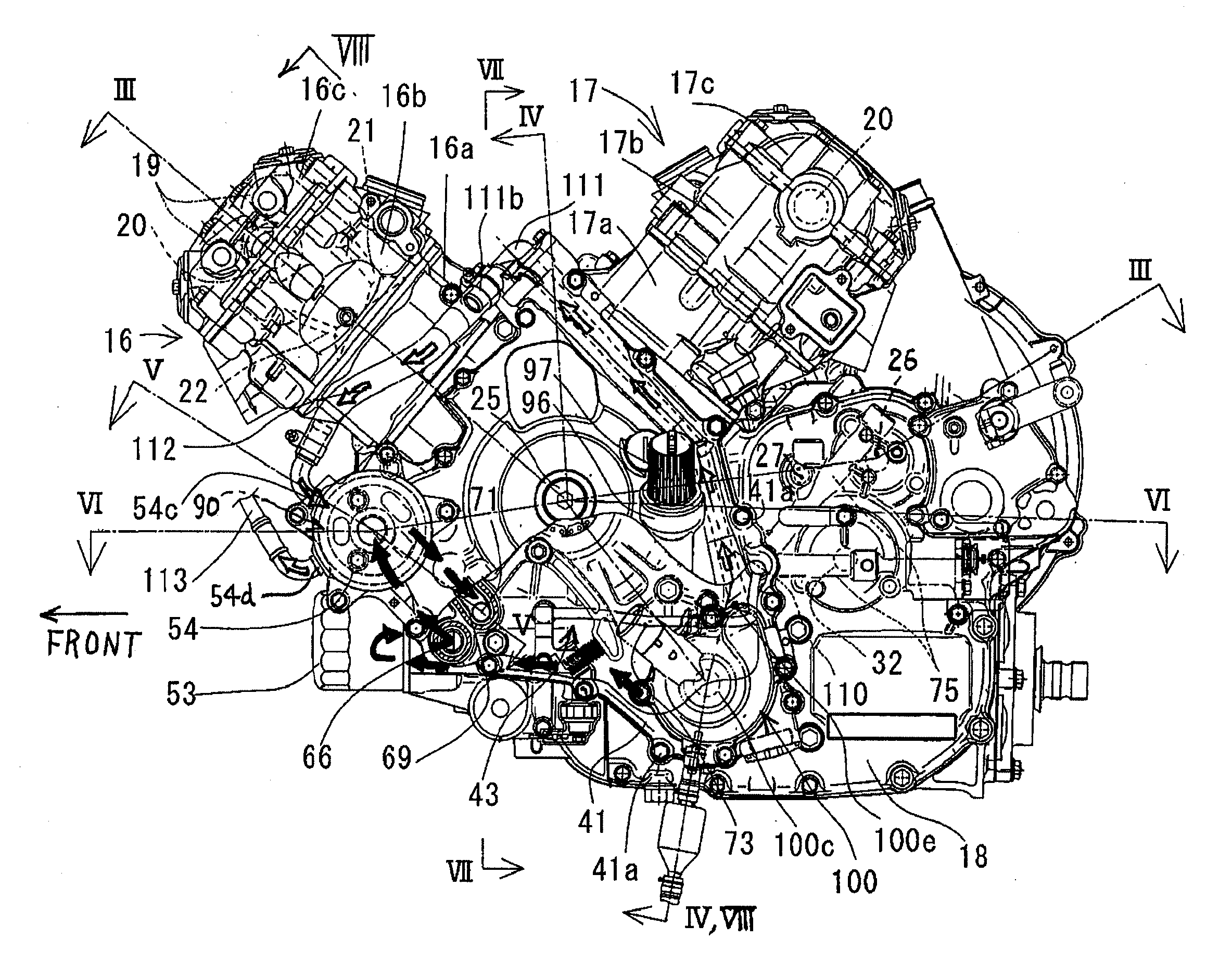
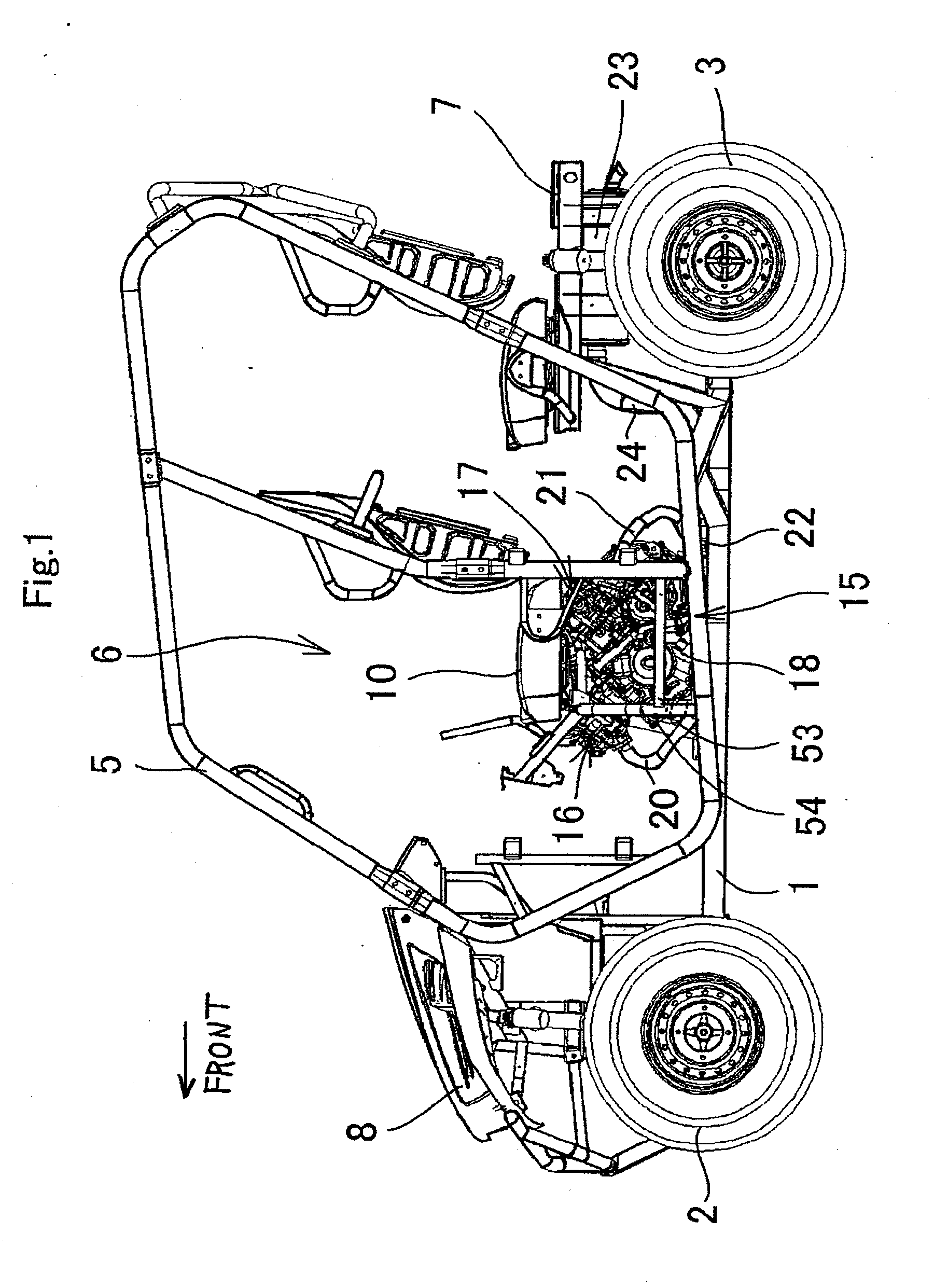
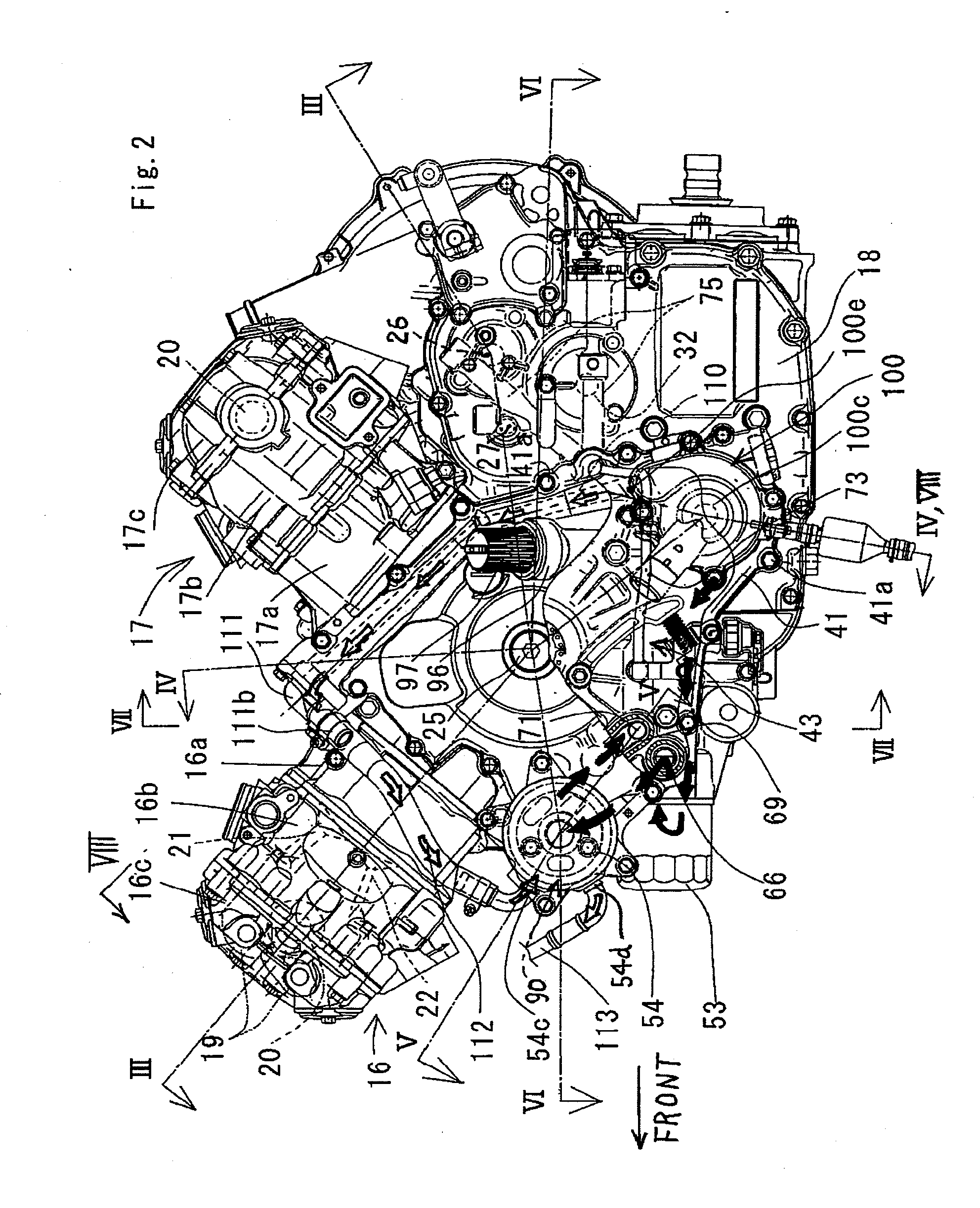
[0036]FIGS. 1 to 8 show an engine having a lubricating oil feeding structure according to the present invention, and a utility vehicle provided with this engine. One embodiment of the present invention will be described based on these figures.

(Structure of Vehicle)

[0037]In FIG. 1, the utility vehicle is provided with a pair of right and left front wheels 2 in a front part of a vehicle body frame 1, a pair of right and left rear wheels 3 in a rear part of the vehicle body frame 1, a cabin 6 surrounded by a cabin frame (ROPS) 5 between the front wheels 2 and the rear wheels 3, a loading platform 7 on the rear side of the cabin 6, and a bonnet 8 and the like on the front side of the cabin 6. A pair of right and left front seats 10 is installed in a front half part in the cabin 6, and a pair of right and left rear seats 11 is installed in a rear half part in the cabin 6. The cabin frame 5 is generally called ROPS which is an abbreviation of rollover protective structure.

[0038]An engine ...


PUM


Abstract

A lubricating oil feeding structure of an engine includes an oil pump provided in a crankcase for pressurizing and feeding oil in an oil reservoir, an oil filter provided in an outer peripheral wall of the crankcase for purifying the oil fed from the oil pump, and an oil cooler provided in a cover member covering an end of the crankcase in the crankshaft direction for cooling the oil sent from the oil filter. Preferably, the cover member is a generator cover, and the oil cooler is arranged on the outer side in the radial direction of a rotor of the generator.

Description

BACKGROUND OF THE INVENTION[0001]1. Field of the Invention[0002]The present invention relates to a lubricating oil feeding structure of an engine, particularly to a lubricating oil feeding structure suitable for an engine of a vehicle.[0003]2. Description of the Related Art[0004]A lubricating oil feeding structure of an engine is generally provided with an oil pump for suctioning lubricating oil (hereinafter simply referred to as the “oil”) in an oil reservoir and feeding, an oil filter for purifying the oil fed from the oil pump, and an oil cooler for cooling the purified the oil.[0005]FIG. 9 is a multi-cylinder engine described in Unexamined Japanese Patent Publication No. 2007-77925. An oil cooler 300 is detachably attached to a front end surface of a crankcase 301, an oil filter 302 is detachably attached to a front end surface of an oil pan 303, and an oil pump (not shown) is provided in a lower portion in the crankcase 301. A water pump 305 for cooling the engine is attached t...

Claims


Application Information

Patent Timeline
Patent Type & Authority Applications(United States)
IPC IPC(8): F01M11/03
CPCF01M1/10F01M11/02F01M5/002
Inventor TAKANO, KIYOHITO
Owner KAWASAKI MOTORS LTD
Learn More