
Interference Mitigation Circuitry for Biometric Measurements

a technology of interference mitigation circuit and biometric signal, which is applied in the field of measuring biometric signals, can solve the problems of non-uniform distribution of electric charges on human skin, variability in properties of impedance circuits, and interference with the measurement of biometric signals

Active Publication Date: 2012-06-21
POLAR ELECTRO
View PDF1 Cites 22 Cited by
  • Summary
  • Abstract
  • Description
  • Claims
  • Application Information

AI Technical Summary

Benefits of technology

The present invention provides an apparatus for measuring biometric signals, such as heart rate, using a differential amplifier and impedance circuitry. The impedance circuitry is designed to have higher impedance on the frequency band of the measured biometric signals than on the outside frequency band. This helps to improve the accuracy and reliability of the signal detection circuitry. The apparatus can be used in a heart rate measurement unit or a casing for connecting multiple skin electrodes. The technical effects of the invention include improved accuracy and reliability of biometric signal detection and improved impedance tuning for the differential amplifier.

Problems solved by technology

Particularly, when carrying out measurements on a moving body, a skin electrode may be in continuous motion with respect to the skin, and the motion causes variance in properties of the impedance circuit.
This interferes with the measurement of the biometric signals.
Furthermore, human skin contains electric charges that are typically distributed non-uniformly.
As a result of these phenomena, for example, electrical charges around one skin electrode are typically different from electrical charges around another skin electrode, which causes interference to the measurement of biometric signals.

Method used


Image

  • Interference Mitigation Circuitry for Biometric Measurements
  • Interference Mitigation Circuitry for Biometric Measurements
  • Interference Mitigation Circuitry for Biometric Measurements

Examples


Embodiment Construction

[0028]The following embodiments are exemplary. Although the specification may refer to “an”, “one”, or “some” embodiment(s) in several locations, this does not necessarily mean that each such reference is to the same embodiment(s), or that the feature only applies to a single embodiment. Single features of different embodiments may also be combined to provide other embodiments. Furthermore, words “comprising” and “including” should be understood as not limiting the described embodiments to consist of only those features that have been mentioned and such embodiments may contain also features / structures that have not been specifically mentioned.

[0029]Embodiments described herein relate to a measurement apparatus or a measurement system configured to measure biometric signals. In an embodiment, the measurement apparatus is configured to measure a heart activity signal of a subject. The heart activity signal comprises electrocardiograph (EKG) or a part thereof, such as P, Q, R, S, or T ...


PUM


Abstract

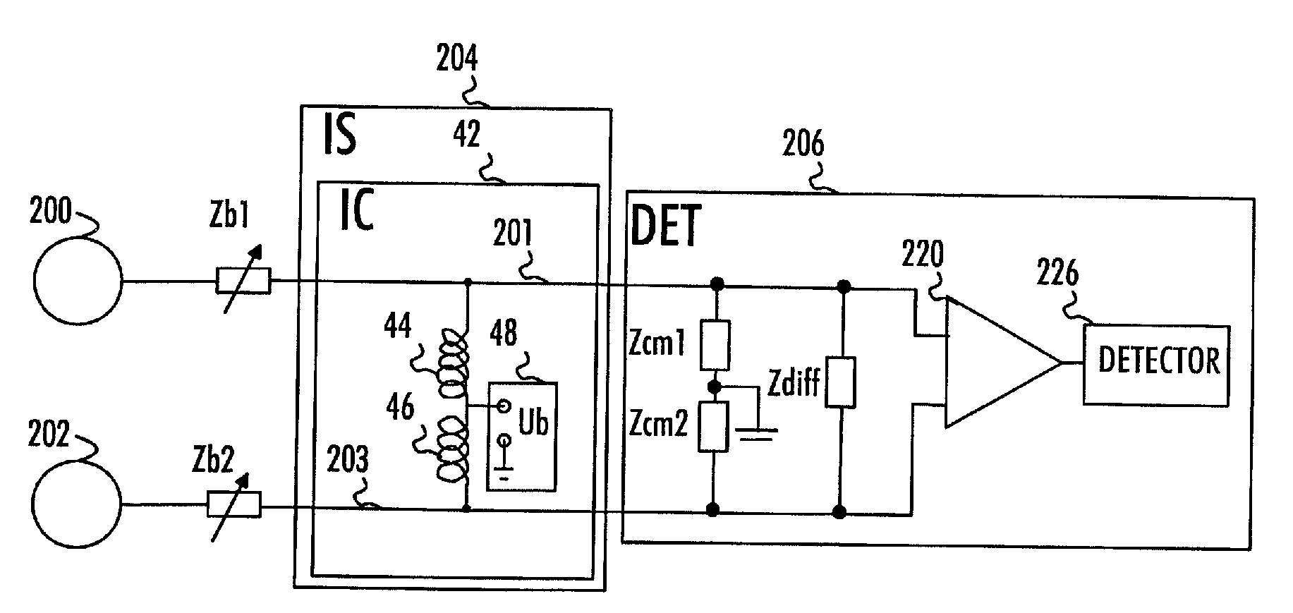
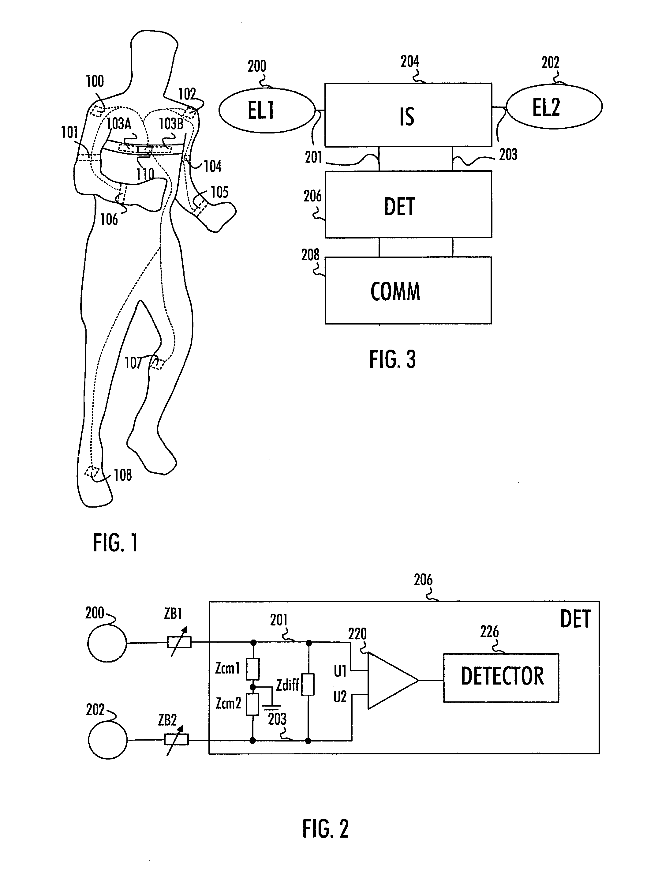
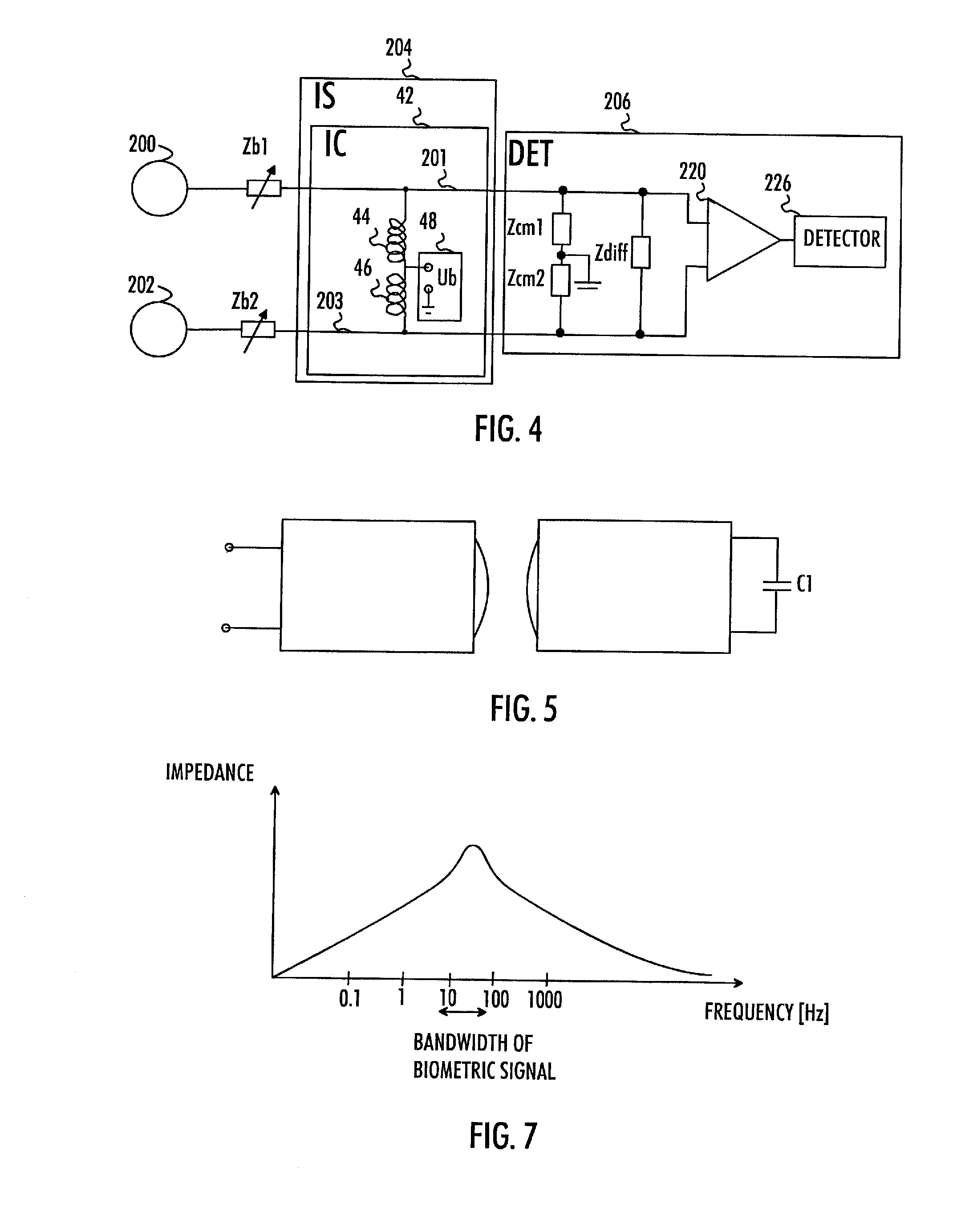
An apparatus includes a first signal line configured to couple signals from a first skin electrode to a first input of a differential amplifier comprised as a front-stage in a signal detection circuitry for measurement of biometric signals sensed by the first skin electrode; a second signal line configured to couple signals from a second skin electrode, different from the first skin electrode, to a second input of the differential amplifier of the signal detection circuitry for measurement of biometric signals sensed by the second skin electrode; and an impedance circuitry coupled between the first signal line and the second signal line in order to tune input impedance of the differential amplifier. Impedance of the impedance circuitry is higher on a first frequency band covering a frequency band of the measured biometric signals than on a second frequency band not covering the frequency band of the measured biometric signals.

Description

CROSS-REFERENCE TO RELATED APPLICATION[0001]This application claims priority based on Finnish Application No. 20106337, filed Dec. 17, 2010, which is incorporated herein by reference.BACKGROUND[0002]1. Field[0003]The invention relates to the field of measuring biometric signals.[0004]2. Description of the Related Art[0005]When measuring biometric signals, skin electrodes are typically in contact with the skin of a subject whose biometric signals are being measured. The skin electrodes sense electric signals, such as electrocardiographic or electromyographic signals, from the human body, and it may be understood that the contact between the skin and a skin electrode forms an impedance circuit. Particularly, when carrying out measurements on a moving body, a skin electrode may be in continuous motion with respect to the skin, and the motion causes variance in properties of the impedance circuit. It may be understood that the motion modulates the impedance of the impedance circuit, the...

Claims


Application Information

Patent Timeline
Patent Type & Authority Applications(United States)
IPC IPC(8): A61B5/0402A61B5/053A61B5/308
CPCA61B5/024A61B5/0408A61B5/0428A61B5/0452A61B5/0531A61B2562/182A61B5/02438A61B5/0245A61B5/04282A61B5/0488A61B5/0006A61B5/25A61B5/30A61B5/349A61B5/26A61B5/256A61B5/308A61B5/305A61B5/28
Inventor PEKONEN, ELIAS
Owner POLAR ELECTRO
Learn More