Bearing oil supply structure for wind turbine generator
a technology for bearing oil and wind turbine generators, which is applied in the direction of gearing details, machines/engines, gearing, etc., can solve the problems of high cost, complicated structure with a large number of components, etc., and achieve the effects of reducing the number of components, simplifying the oil supply system, and simplifying the assembly thereo
- Summary
- Abstract
- Description
- Claims
- Application Information
AI Technical Summary
Benefits of technology
Problems solved by technology
Method used
Image
Examples
first embodiment
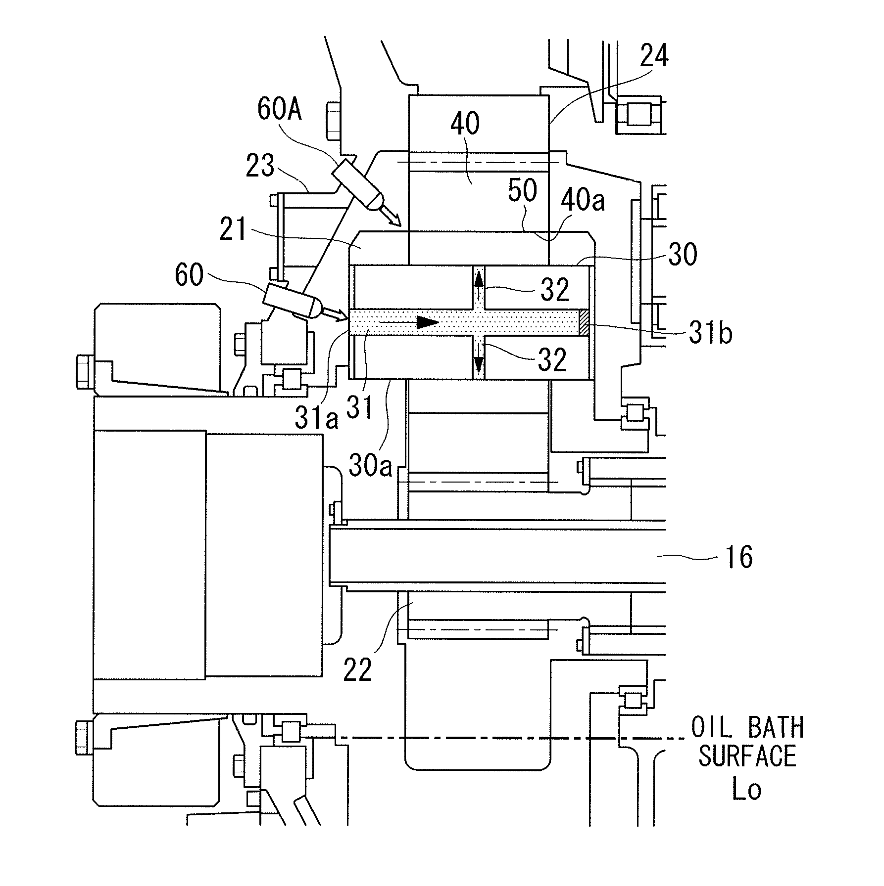
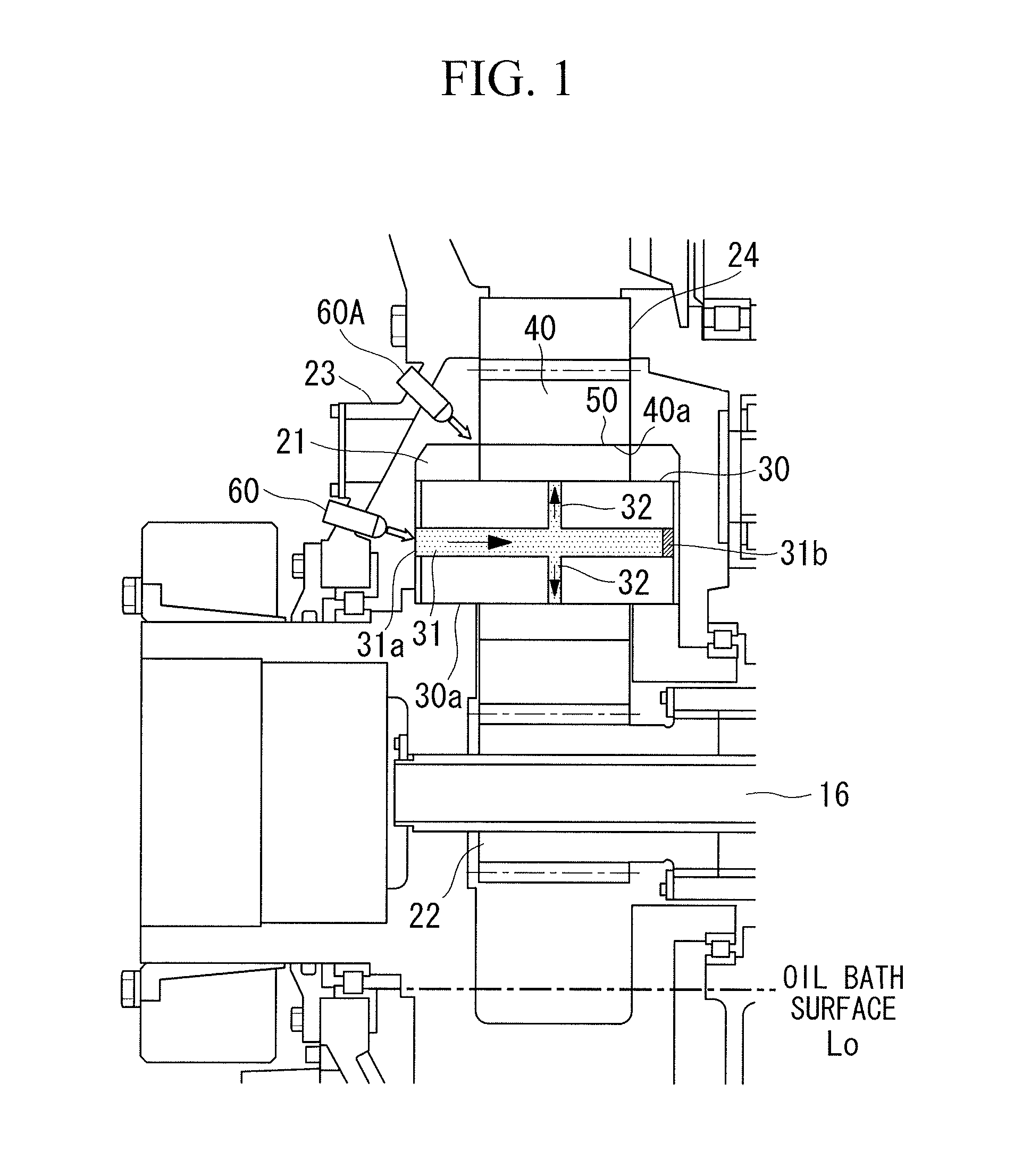
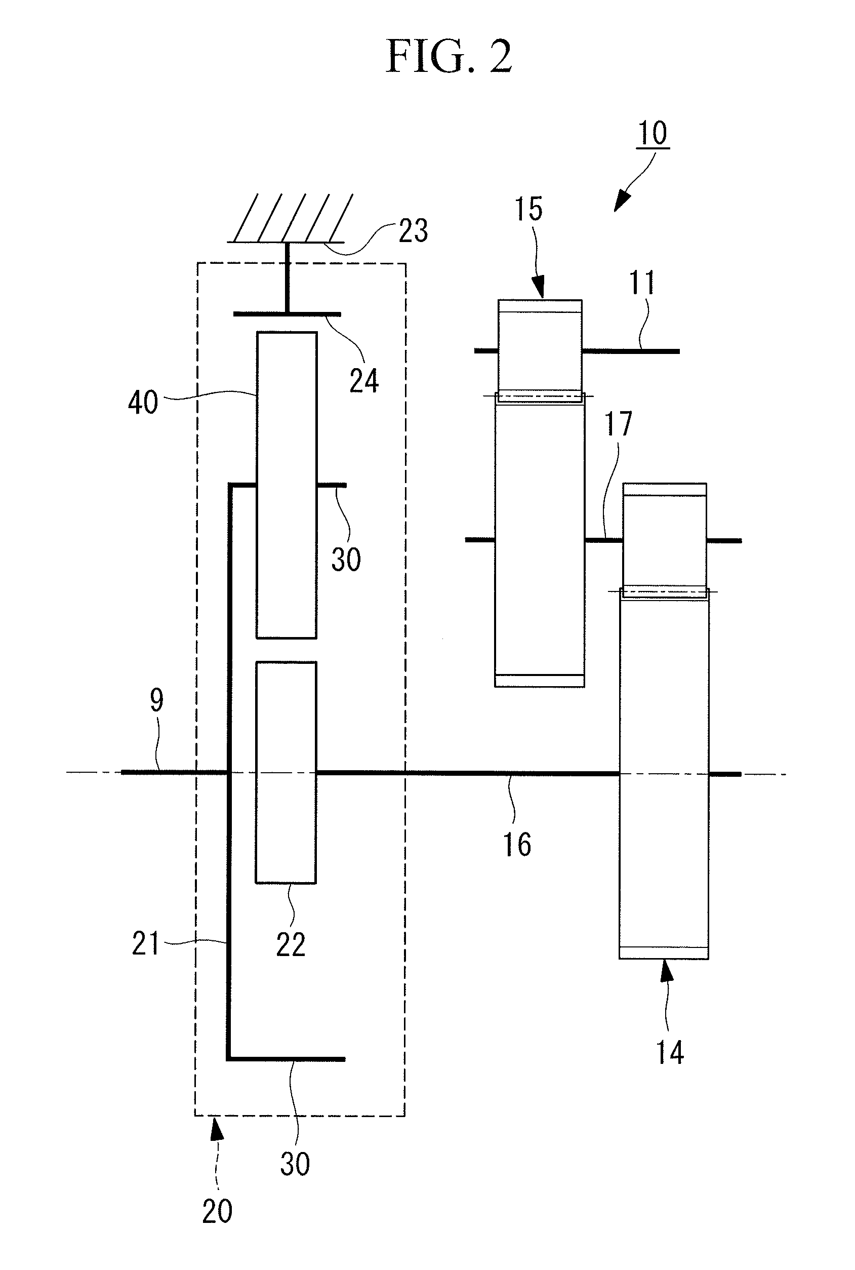
[0039]A bearing oil supply structure for a wind turbine generator according to the present invention is suitable for a gear box having a planetary-type planet gear box mechanism of a wind turbine generator and in particular a gear box that has slide bearings as planet bearings.
[0040]FIG. 4 shows a wind turbine generator 1 comprising a tower (referred to also as a pole) 2 standing on a base B, a nacelle 3 installed on the upper end of the tower 2, and a rotor head 4 provided on the front end of the nacelle 3 and supported so as to be rotatable about a substantially horizontal transverse axis of rotation.
[0041]The rotor head 4 is provided with a plurality of (three, for example) blades 5 radially arranged about the axis of rotation. The force of wind hitting the blades 5 in the direction of the axis of rotation of the rotor head 4 is converted into a mechanical power to make the rotor head 4 rotate about the axis of rotation.
[0042]The nacelle 3 is provided with an anemometer 7 for mea...
second embodiment
[0061]Next, a wind turbine generator according to a second embodiment of the present invention will be described with reference to FIG. 6. The same components as those in the embodiment described above are denoted by the same reference numerals, and detailed descriptions thereof will be omitted.
[0062]According to this embodiment, as shown in FIG. 6, for example, a lubricant oil receiving pan 70 is provided at the lubricant oil inlet 31a for receiving the lubricant oil injected through a nozzle 60B and guiding the lubricant oil into the main lubricant oil channel 31. The lubricant oil receiving pan 70 has the shape of a gutter formed by bending a plate into a substantially L-shaped cross section, for example, so that the lubricant oil receiving pan 70 accumulates the lubricant oil injected downward through the nozzle 60B with reliability and guides the lubricant oil into the main lubricant oil channel 31. Viewed from the axial direction of coupling to the main shaft 9, the lubricant ...
third embodiment
[0066]Next, a wind turbine generator according to a third embodiment of the present invention will be described with reference to FIGS. 7 to 9. The same components as those in the embodiments described above are denoted by the same reference numerals, and detailed descriptions thereof will be omitted.
[0067]According to this embodiment, lubrication of the slide bearings is achieved by supplying lubricant oil by using an oil bath in the lower rotation region and by supplying lubricant oil reserved during oil bathing in the upper rotation region. That is, in this embodiment, the forced lubrication by injecting the lubricant oil through the nozzle 60 described above is not performed.
[0068]More specifically, according to the embodiment shown in FIG. 7, the same main lubricant oil channel 31 and radial lubricant oil channel 32 as those in the embodiment described above are formed in the planet pin 30. At the lubricant oil inlet 31a, a lubricant oil receiving pan 71 having a substantially ...
PUM
 Abstract
Description
Claims
Application Information
 - R&D
- Intellectual Property
- Life Sciences
- Materials
- Tech Scout
- Unparalleled Data Quality
- Higher Quality Content
- 60% Fewer Hallucinations
Browse by: Latest US Patents, China's latest patents, Technical Efficacy Thesaurus, Application Domain, Technology Topic, Popular Technical Reports.
© 2025 PatSnap. All rights reserved.Legal|Privacy policy|Modern Slavery Act Transparency Statement|Sitemap|About US| Contact US: help@patsnap.com


