
Ion conductor and electrochromic display device

a display device and electrochromic technology, applied in the direction of capacitors, basic electric elements, instruments, etc., can solve the problems of slow response speed of electrochromic display devices, difficulty in displaying multiple colors, and difficulty in using display devices such as electronic papers,

Active Publication Date: 2012-06-21
RICOH KK
View PDF5 Cites 31 Cited by
  • Summary
  • Abstract
  • Description
  • Claims
  • Application Information

AI Technical Summary

Benefits of technology

[0018]According to an aspect of the present invention, an ion conductor includes a mixture that including an electrolyte including a salt including inorganic or organic pairs of negative and positive ions, and a low-molecular liquid crystal material. ...

Problems solved by technology

However, when any of the above method is used, it may still be very difficult to display multiple colors while maintaining a higher white reflectivity and a higher contrast ratio.
As a result, it may become difficult to use the display device as such as an electronic paper.
On the other hand, the electrochromic display device may have the drawback of a slow response speed in coloring / decoloring (developing and disappearing a color) because the coloring / decoloring is performed based on redox reactions.
On the other hand, when the electrolyte layer is in a liquid form, the strength and the reliability of the device may be degraded.
Therefore, a leakage of the electrolyte solution, and drying in the battery due to the volatilization of the solvent may occur.
Further, in a typical battery case, the electrolyte solution may be unevenly distributed.
Due to the uneven distribution of the electrolyte solution, a part of a separation membrane may dry.
As a result, internal impedance may increase and an internal short-circuit may also occur.
Therefore, in the electrochromic display device, it may be difficult to completely seal the electrolyte with a metal or the like.
As a result, in the electrochromic display device, leakage of the electrolyte solution and drying in the battery due to volatilization of the solvent may become a serious problem.
This lower electrical conductivity may be a (serious) problem in practical use.
However, the electrolyte layers in related art may not be sufficient for the electrochromic display use.
On the other hand, condurrently, the memory effect of the image display is more likely to be degraded.
In this open-circuit configuration, however, when ions diffusively move in the electrolyte layer, the oxidation state or the reduction state may become unstable.
As a result, it may become difficult to maintain the charged colored state.
As a result, the display image may blur.
However, when this configuration is used in, for example, a high-resolution display, the blur in the display image may become remarkable.
However, when this configuration is used, the blurring speed of the display image may be increased.
However, this configuration may be too complicated, so that it may be difficult to manufacture this configuration, and the cost may be greatly increased.
As described above, in the electrochromic display device in related art, it may still be difficult to achieve sufficient response speed in coloring and decoloring a color, sufficient memory characteristics, and sufficient reliability of the devices.

Method used

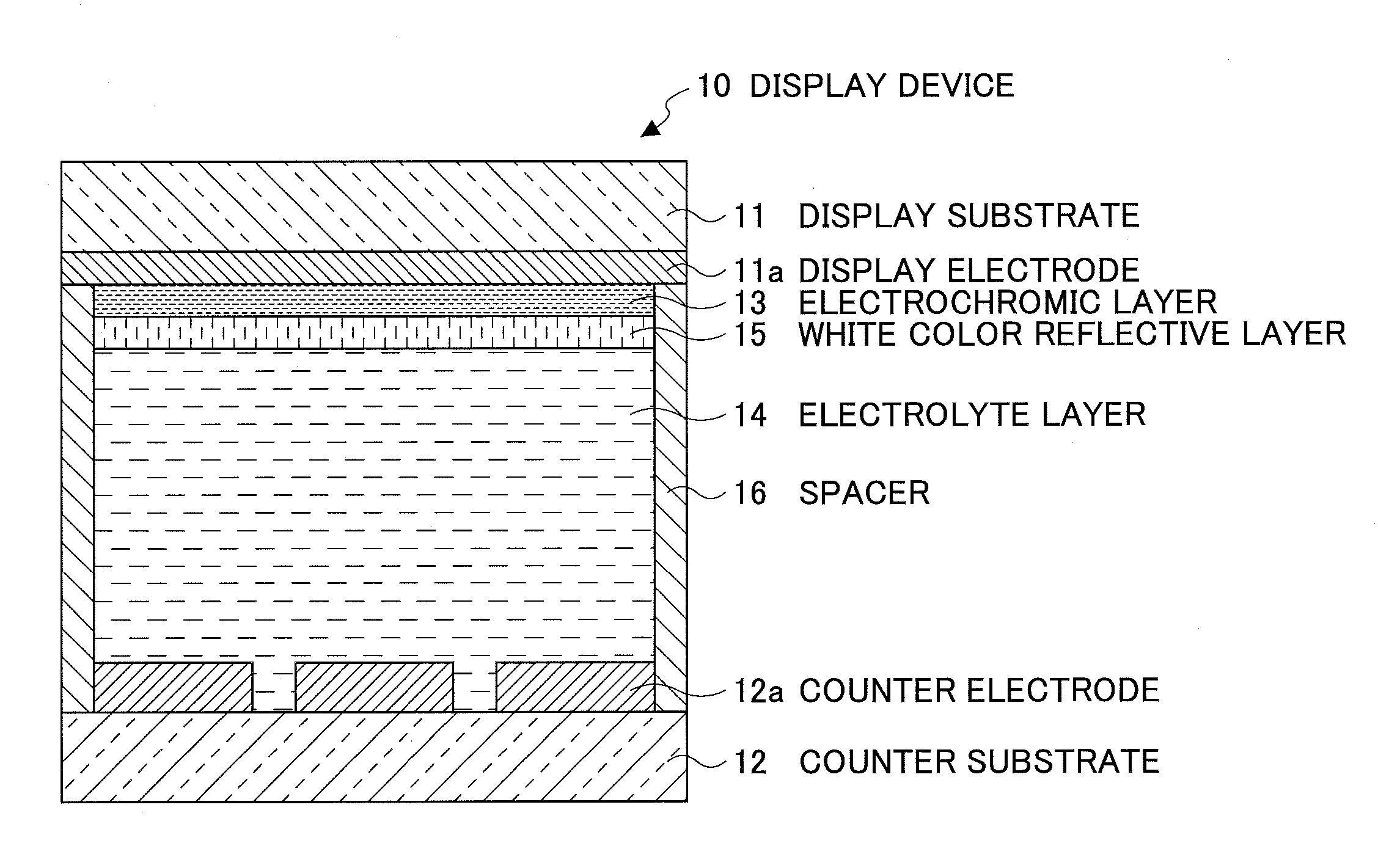
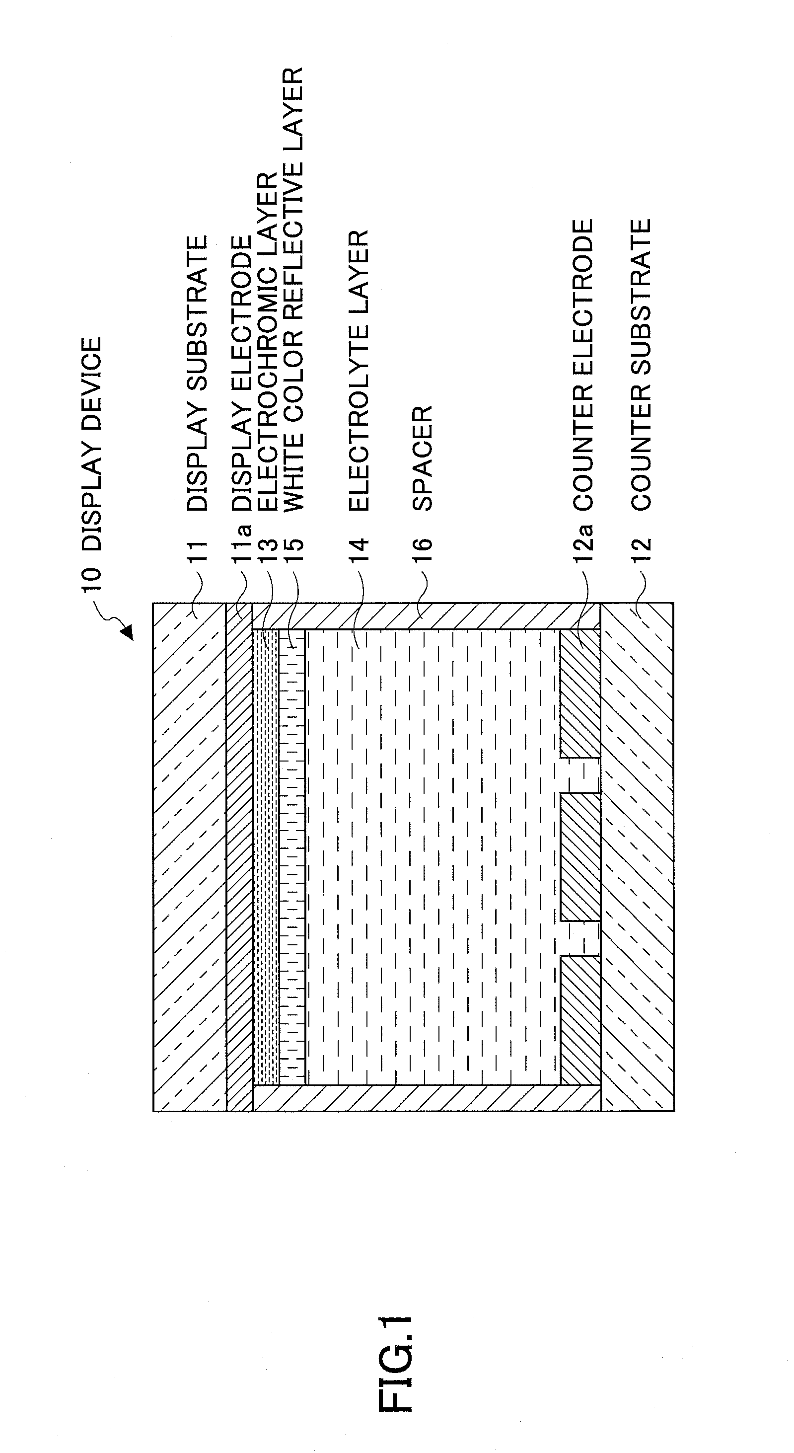
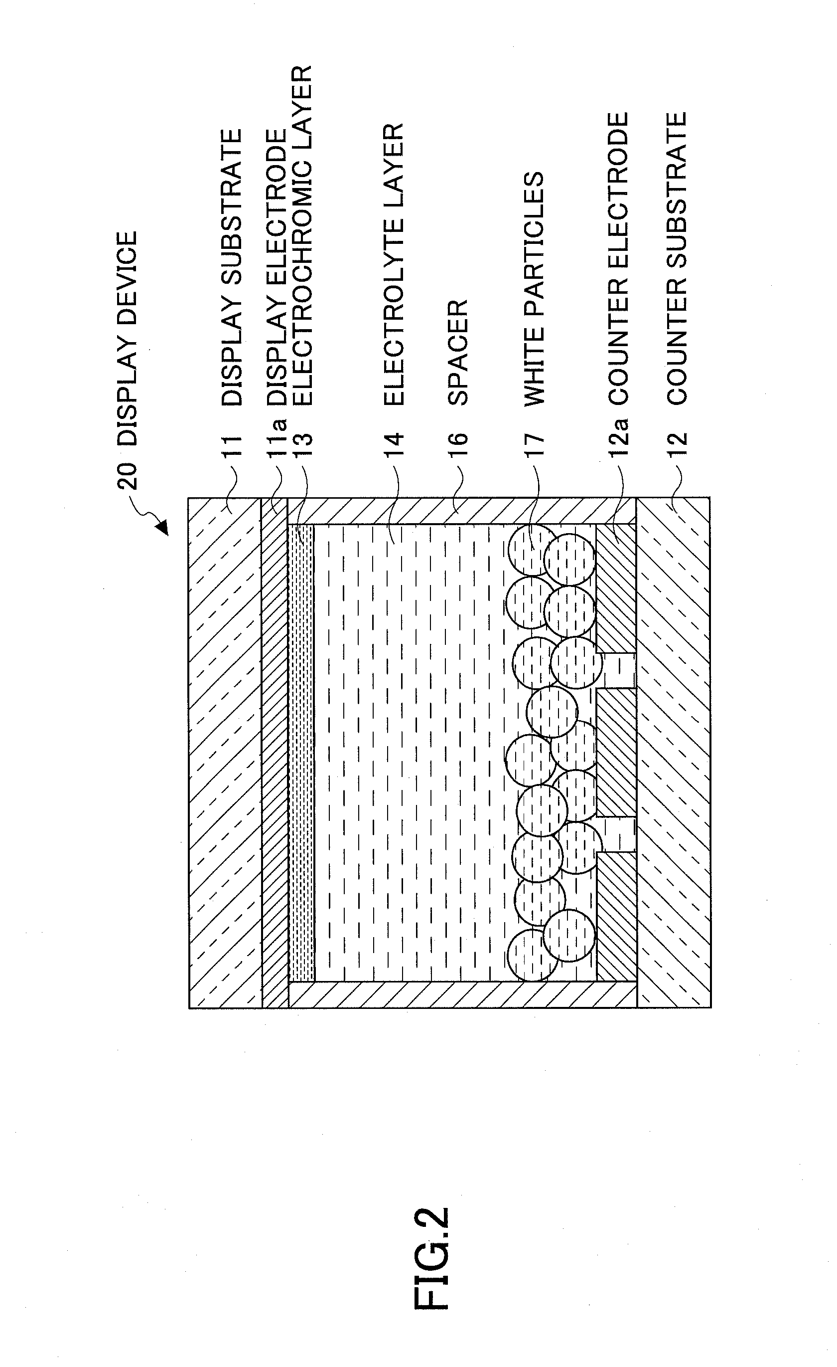

Image

  • Ion conductor and electrochromic display device
  • Ion conductor and electrochromic display device
  • Ion conductor and electrochromic display device

Examples


example 1

[Manufacturing Electrochromic Display Device]

[0116]As the display electrode, a glass substrate having sizes of 40 mm (vertical) by 40 mm (lateral) and a thickness of 0.7 mm was provided. On this glass substrate, an ITO film having a thickness of approximately 100 nm was formed to form the display electrode 11a.

[0117]Next, titanium oxide particle dispersion liquid (product name: SP210 by Showa titanium Co., Ltd. average particle diameter: approximately 20 nm) was coated using a spin coat method. Then, the annealing treatment to heat at a temperature of approximately 120° C. for approximately 15 minutes was performed to form a titanium oxide particulate film (formed of a nano-structure semiconductor material) having a thickness of approximately 1.0 μm. Next, 2,2,3,3-tetrafluorophloropropanol solution containing 1.5 wt % of compound represented by the following structural formula (3) as the electrochromic compound was applied by the spin coat method. Then, the annealing treatment to h...

example 2

[0133]In Example 2, the display device and the impedance measurement cell were manufactured in the same manner as in Example 1 except that 4-cyano-4′-pentylbiphenyl (product name: C1550, Tokyo Chemical Industry Co., Ltd., molecular weight: 249) as the liquid crystal material of the electrolyte layer used in Example 1 was replaced by a mixture of 4-cyano-4′-pentylbiphenyl and 4-cyano-4′-pentyloxybiphenyl (product name: C1551, Tokyo Chemical Industry Co., Ltd., molecular weight: 267) (weight composition ratio: 7 / 3). Then, the display device and the impedance measurement cell of Example 2 were evaluated. Table 1 further collectively illustrates evaluation results (coloring characteristics, memory characteristics) of the electrolyte layer (liquid crystal material, electrolyte and the like) and display device and evaluation results (impedance, voltage response and the like) of the electrolyte layer cell used in Example 2. As a result, similar to Example 1, it was possible to detect (obse...

example 3

[0134]In Example 3, the display device and the impedance measurement cell were manufactured in the same manner as in Example 2 except that the amount of electrolyte (1.5 wt % mixture) in Example 2 was replaced by a larger amount of electrolyte (2 wt % mixture). Then, the display device and the impedance measurement cell of Example 3 were evaluated. Table 1 further collectively illustrates evaluation results (coloring characteristics, memory characteristics) of the electrolyte layer (liquid crystal material, electrolyte and the like) and display device and evaluation results (impedance, voltage response and the like) of the electrolyte layer cell used in Example 3. As a result, similar to Example 1, it was possible to detect (observe) the coloring / decoloring response, and also excellent memory characteristics were confirmed (observed).


PUM


Abstract

An ion conductor includes a mixture including an electrolyte including a salt including inorganic or organic pairs of negative and positive ions, and a low-molecular liquid crystal material. Further, an impedance of the ion conductor varies in accordance with an increase of a voltage applied to the ion conductor due to an orientation response of the low-molecular liquid crystal material, the impedance being determined by an AC impedance method.

Description

CROSS-REFERENCE TO RELATED APPLICATION[0001]The present application claims priority under 35 U.S.C §119 to Japanese Patent Application Nos. 2010-282033 filed Dec. 17, 2010, and 2011-245726 filed Nov. 9, 2011, the entire contents of which are hereby incorporated herein by reference.BACKGROUND OF THE INVENTION[0002]1. Field of the Invention[0003]The present invention generally relates to an ion conductor and an electrochromic display device, and more particularly to a new ion conductor in which ion mobility may be changed by an applied voltage, and an electrochromic display device using the ion conductor and having faster response speed of coloring and decoloring and excellent memory characteristics.[0004]2. Description of the Related Art[0005]Recently, extensive research has been made in the field of an electronic paper as an electronic medium which is replacing a paper medium. Although being a display device, the electronic paper is expected to be used just like ordinary paper. Ther...

Claims


Application Information

Patent Timeline
IPC IPC(8): G02F1/153G02F1/139G02F1/155B82Y99/00G02F1/1516
CPCG02F1/1525G02F1/15G02F1/1516
Inventor YASHIRO, TOHRUHIRANO, SHIGENOBUFUJIMURA, KOHNAIJO, YOSHIHISAOKADA, YOSHINORITAKAHASHI, HIROYUKIMURAKAMI, AKISHIGE
Owner RICOH KK
Learn More