
Liquid crystal display

a liquid crystal display and display technology, applied in non-linear optics, instruments, optics, etc., can solve the problems of large power consumption of conventional direct type lcd, flickering or color breakage, and large optical energy consumption, so as to reduce the power consumption of lcd, reduce the loss of light in the color filter, and increase the light transmittance of the color filter.

Inactive Publication Date: 2012-06-21
RES COOPERATION FOUND OF YEUNGNAM UNIV
View PDF3 Cites 12 Cited by
  • Summary
  • Abstract
  • Description
  • Claims
  • Application Information

AI Technical Summary

Benefits of technology

The present invention relates to a liquid crystal display (LCD) that has decreased power consumption, reduced number of light emitting diodes (LEDs), and improved color image resolution. The invention uses a lenticular lens array to transmit red, green, and blue light from a direct type LCD television to a liquid crystal panel. The invention also includes a method for realizing a color image using a field sequential color (FSC) technology that removes the color filter that causes the most light energy loss. However, the FSC technology needs to have a speed of circuit for adjusting an image that is about 6 times faster than a general circuit for adjusting an image, and flickering or color break-up may occur in an LCD using the FSC technology.

Problems solved by technology

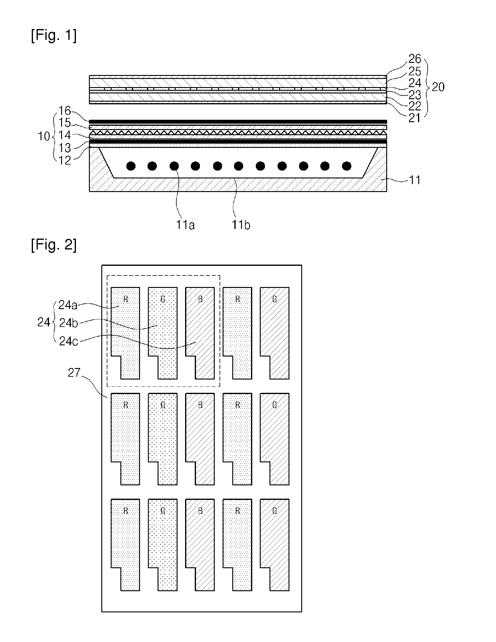
However, in the conventional direct type LCD, a considerable amount of optical energy is lost at the polarizing sheets 21 and 26, an aperture ratio of the liquid crystal pixel 23, and the color filter 24, and thus the conventional direct type LCD consumes large amount of power.
However, although the FSC technology is making remarkable progress, a speed of a circuit for adjusting an image needs to be about 6 times of a general circuit for adjusting an image, and flickering or color break-up may occur in an LCD using the FSC technology.
Accordingly, the LCD using the FSC technology has not yet been put to practical use.

Method used


Image

  • Liquid crystal display
  • Liquid crystal display
  • Liquid crystal display

Examples


Embodiment Construction

[0052]Hereinafter, the present invention will be described more fully with reference to the accompanying drawings, in which exemplary embodiments of the invention are shown. The invention may, however, be embodied in many different forms and should not be construed as being limited to the embodiments set forth herein; rather, these embodiments are provided so that this disclosure will be thorough and complete, and will fully convey the concept of the invention to those skilled in the art. Meanings of terms and words used herein are not limited to common or dictionary definitions, and are understood according to technical aspects of the present invention, because an inventor is allowed to define a term or word to best describe the invention.

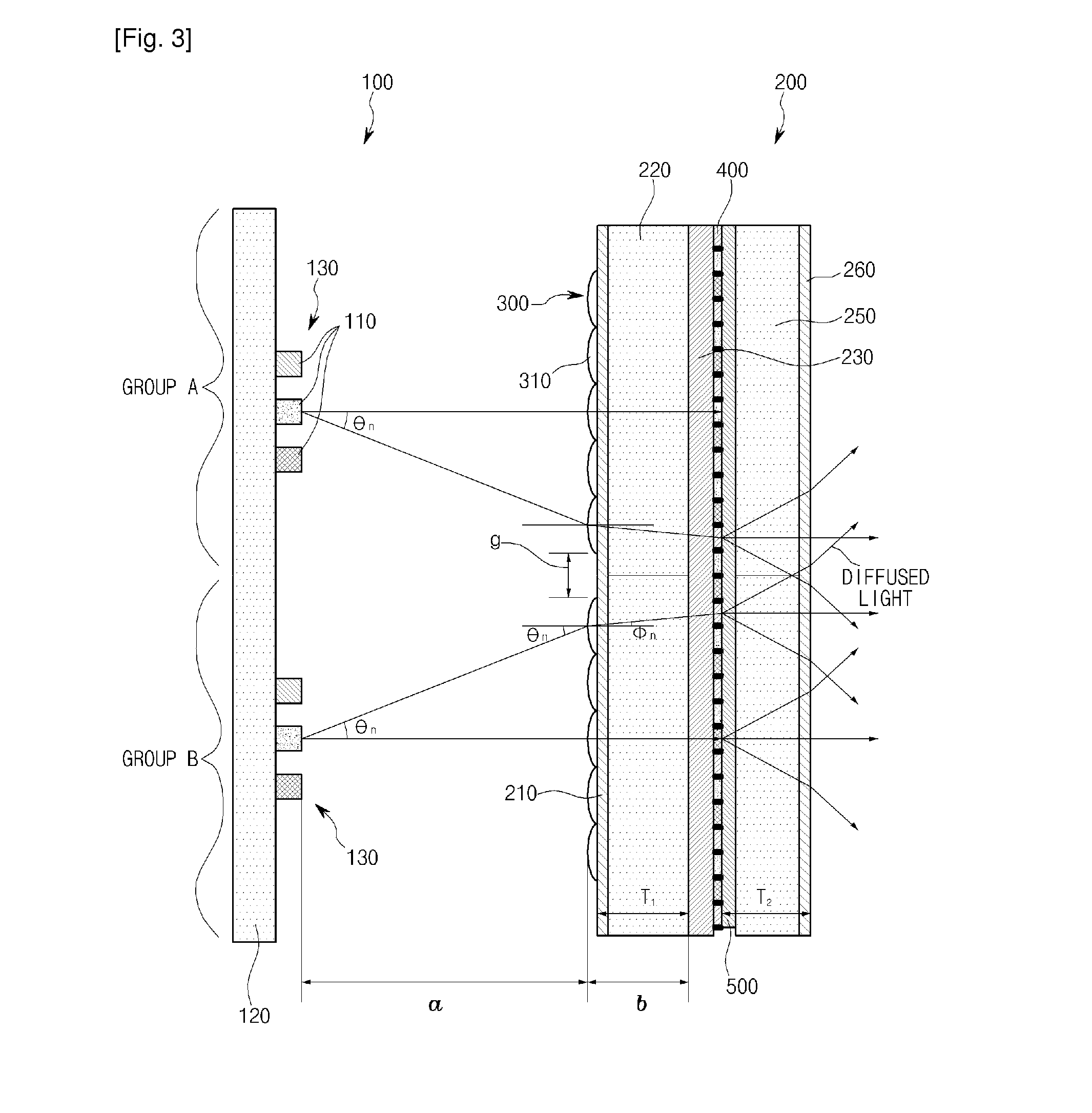
[0053]FIG. 3 is a cross-sectional diagram for describing a concept of a liquid crystal display (LCD) including a lenticular lens array 300, according to an embodiment of the present invention.

[0054]Referring to FIG. 3, the LCD includes a liquid cr...


PUM

PropertyMeasurementUnit
total internal reflectionaaaaaaaaaa
transparentaaaaaaaaaa
thicknessaaaaaaaaaa

Abstract

A liquid crystal display including: a liquid crystal panel including front and rear glass substrates, a plurality of liquid crystal sub-pixels for red, green, and blue respectively corresponding to three color, i.e., red, green, and blue, lights, and disposed between the front and rear glass substrates, and a color filter disposed between the plurality of liquid crystal sub-pixels and the front glass substrate; a backlight unit disposed behind the liquid crystal panel, and including a plurality of three color light suppliers spaced apart from each other in groups and supplying the three color lights; and a lenticular lens array disposed between the backlight unit and the liquid crystal panel, and inducing the three color lights emitted from the three color light suppliers to the liquid crystal sub-pixels and the color filter of the liquid crystal panel. According to the liquid crystal display, the lenticular lens array is attached to the liquid crystal panel so as to induce red, green, and blue lights respectively to red, green, and blue color filters inside the liquid crystal panel, thereby increasing light transmittance and decrease light loss. Accordingly, power consumption of the liquid crystal display is reduced, the liquid crystal display realizes high resolution, and manufacturing expenses of the liquid crystal display are reduced.

Description

TECHNICAL FIELD [0001]The present invention relates to a liquid crystal display (LCD), and more particularly, to a LCD having decreased power consumption, having a decreased number of light emitting diodes (LEDs), and realizing a color image having high definition and high resolution, as light transmittance is improved by directly transmitting red, green, and blue light from a direct type LCD television respectively to red, green, and blue liquid crystal sub-pixels and red, green, and blue color filers, by using a lenticular lens array, wherein the red, green, and blue liquid crystal sub-pixels and the red, green, and blue color filters are sequentially installed on a liquid crystal panel.BACKGROUND ART [0002]FIG. 1 is a cross-sectional diagram of a conventional direct type liquid crystal display (LCD), and FIG. 2 is a plan view illustrating a structure of color filters 24 installed inside a front glass substrate 25 of a liquid crystal panel 20 of FIG. 1.[0003]First, referring to FI...

Claims


Application Information

Patent Timeline
Patent Type & Authority Applications(United States)
IPC IPC(8): G02F1/13357
CPCG02F1/133621G02F1/133526G02F1/1335
Inventor KWON, JIN HYUK
Owner RES COOPERATION FOUND OF YEUNGNAM UNIV
Learn More