Semiconductor Element Control Device and In-Vehicle Electrical System
- Summary
- Abstract
- Description
- Claims
- Application Information
AI Technical Summary
Benefits of technology
Problems solved by technology
Method used
Image

Examples
first embodiment
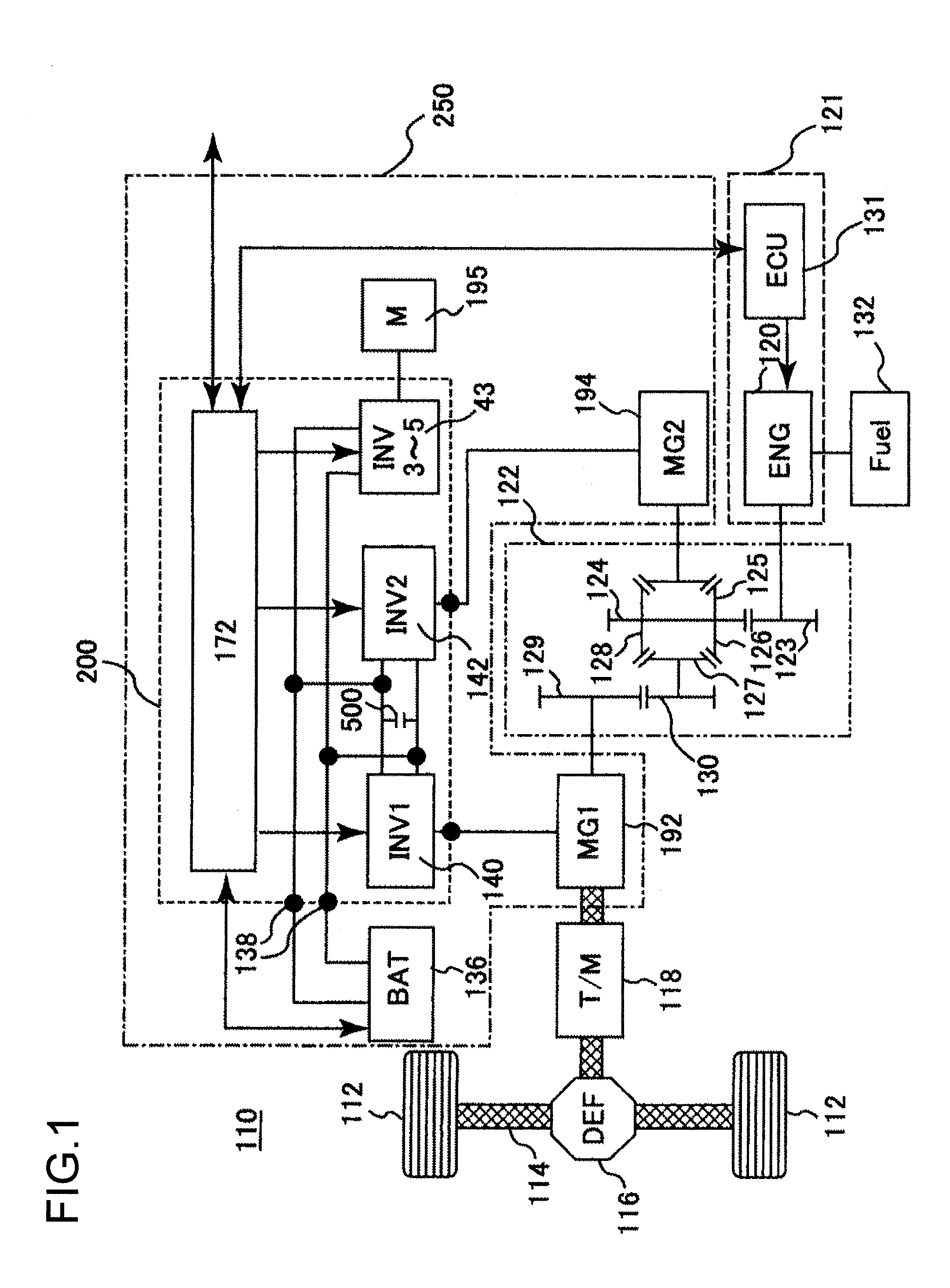
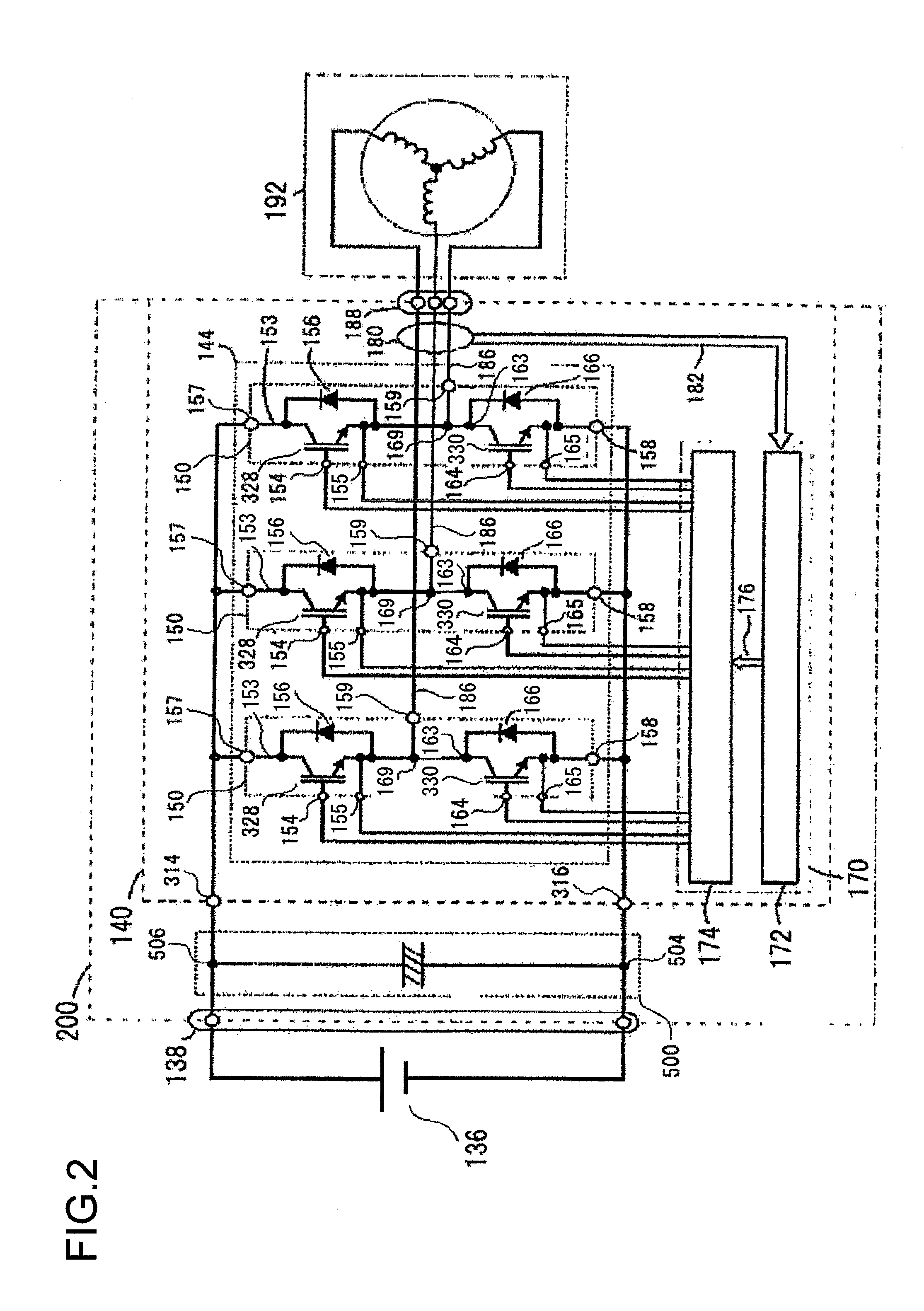
[0028]In the embodiment hereinafter described, the semiconductor element control device and an electrical machine system to be mounted on a vehicle with reference to the drawings. The semiconductor element control device according to an embodiment of the present invention is equipped in a power inverter which converts from DC power to AC power or from AC power to DC power and controls semiconductor elements which perform switching operations to perform such conversion of an electric power. A power inverter having a semiconductor element control device in accordance with the embodiment of the present invention is applicable to hybrid vehicles and ordinary electric vehicles. The control configuration and the circuit configuration of the power inverter to which the power inverter in accordance with the embodiment of the present invention is applied will be described with reference to the FIGS. 1 and 2. FIG. 1 shows a control block diagram for a hybrid vehicle. FIG. 2 is a circuit diagr...
second embodiment
[0078]Next, a second embodiment of the present invention will be explained. In this embodiment, a different semiconductor element control device is used from the one explained above for the first embodiment. It should be understood that since, for this embodiment, the circuit structure of the control blocks and the in-vehicle control system of the hybrid automobile are the same as those for the first embodiment as shown in FIGS. 1 and 2, accordingly explanation thereof will be omitted.
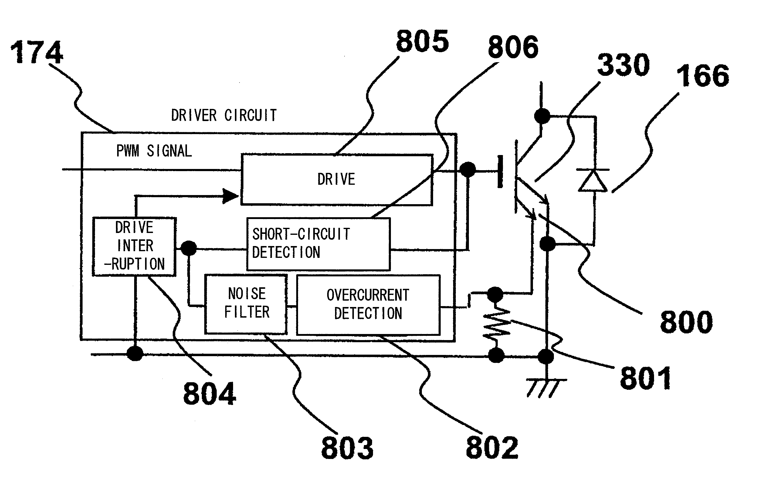
[0079]FIG. 6 is a circuit block diagram of a semiconductor element control device related to this embodiment, FIG. 7 is a circuit diagram of this semiconductor element control device related to this embodiment, and FIG. 8 is a time chart for this semiconductor element control device related to this embodiment during operation. It should be understood that in FIGS. 6 through 8, to portions that are the same as or that correspond to ones for the first embodiment, the same reference numerals as in FIGS. 3...
embodiment # 1
Variant Embodiment #1
[0099]The circuit block diagram of FIG. 9 shows a variant of the second embodiment described above. The aspect by which the circuit shown in FIG. 6 and the circuit shown in FIG. 9 are different is the feature that, by contrast to the case in FIG. 6 in which short-circuit detection and overcurrent detection were performed on the basis of the gate voltage and the sense voltage, in the case of FIG. 9 short-circuit detection and overcurrent detection are performed on the basis of the collector voltage and the sense voltage. Similar beneficial effects to those explained in connection with the second embodiment are obtained using this circuit as well.
PUM
 Abstract
Description
Claims
Application Information
 - R&D Engineer
- R&D Manager
- IP Professional
- Industry Leading Data Capabilities
- Powerful AI technology
- Patent DNA Extraction
Browse by: Latest US Patents, China's latest patents, Technical Efficacy Thesaurus, Application Domain, Technology Topic.
© 2024 PatSnap. All rights reserved.Legal|Privacy policy|Modern Slavery Act Transparency Statement|Sitemap