
Optimizing data rate of multi-band multi-carrier communication systems

a multi-carrier communication and data rate technology, applied in the field of communication systems, can solve problems such as data packet corruption in communication networks

Inactive Publication Date: 2012-06-07
QUALCOMM INC
View PDF3 Cites 18 Cited by
  • Summary
  • Abstract
  • Description
  • Claims
  • Application Information

AI Technical Summary

Benefits of technology

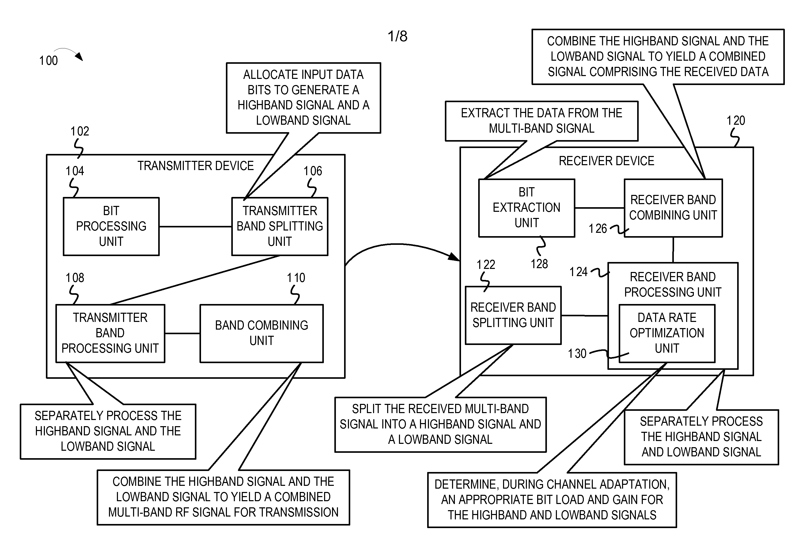
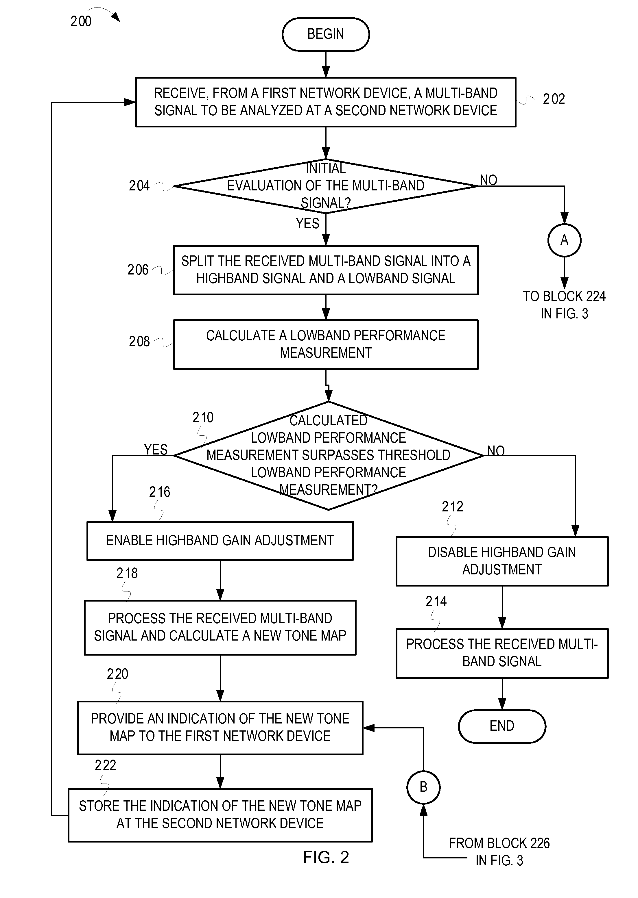
[0003]Various embodiments for optimizing the data rate of multi-band multi-carrier communication systems are disclosed. In one embodiment, a multi-band signal is received at a first network device of a communication system from a second network device of the communication system during a channel adaptation mode. The multi-band signal is split into a plurality of independent frequency band signals. A performance measurement of a first of the plurality...

Problems solved by technology

However, both wired and wireless communication networks can be subject to a wide variety of noise and interference sources, which can corrupt data packets exchanged via the communication networks.

Method used


Image

  • Optimizing data rate of multi-band multi-carrier communication systems
  • Optimizing data rate of multi-band multi-carrier communication systems
  • Optimizing data rate of multi-band multi-carrier communication systems

Examples


second embodiment

[0044]FIG. 5 is an example block diagram of a mechanism for optimizing the data rate of a multi-band multi-rate communication. FIG. 5 depicts a multi-band multi-carrier communication system 500 in a single DAC / single ADC, shared filter configuration. The communication system 500 comprises a DAC 502 coupled to the transmitter band-splitting unit 106. The transmitter band-splitting unit 106 splits the input data bits into N independent frequency bands. When the communication system 500 operates in a “data transmit” mode, the N independent frequency band outputs 514A, 514N at the transmitter band-splitting unit 106 are coupled to corresponding N filters 504A, 504N. In FIG. 5, data on one frequency band at output terminal 514A of the transmitter band-splitting unit 106 is coupled to terminal 516A of (and is provided as input to) the filter 504A. Likewise, data on another frequency band at output terminal 514N of the transmitter band-splitting unit 106 is coupled to terminal 516N of (and...

third embodiment

[0048]FIG. 6 is an example block diagram of a mechanism for optimizing the data rate of a multi-band multi-rate communication. FIG. 6 depicts a multi-band multi-carrier communication system 600 in a single DAC / single ADC, shared filter and shared gain stage configuration. The communication unit 600 comprises the DAC 502 coupled to a band-splitting unit 602. When the communication system 600 operates in the “data transmit” mode, the DAC 502 is coupled to the band-splitting unit 602. This is achieved by coupling an output terminal 608 of the DAC 502 to an input terminal 610 of the band-splitting unit 602. In the “data transmit” mode, the band-splitting unit 602 splits the input data bits into N independent frequency bands. The band-splitting unit 602 is coupled to N filters 604A, 604N. Also, each of the N filters 604A, 604N are respectively coupled to gain stages 606A, 606N. In FIG. 6, the output of the filter 604A is provided as an input to the gain stage 606A. Likewise, the output o...


PUM


Abstract

Wired and wireless communication networks can be subject to noise and interference resulting data corruption. In a communication system comprising a first network device and a second network device, the first and the second network devices can be configured for optimizing the data rate of the communication system. On receiving a multi-band signal at the first network device from the second network device during a channel adaptation mode, the multi-band signal can be split into a plurality of independent frequency band signals. A performance measurement of a first of the plurality of frequency band signals corresponding to a lowest frequency band signal can be calculated. Communication parameters can be determined for each of the plurality of frequency band signals based on the performance measurement of the first of the plurality of frequency band signals. The communication parameters can be provided from the first network device to the second network device.

Description

BACKGROUND[0001]Embodiments of the inventive subject matter generally relate to the field of communication systems and more particularly, to optimizing the data rate of multi-band multi-carrier communication systems.[0002]Electronic devices can use wired or wireless communication networks for data communication. In one example, electric power lines typically used for distributing electric power to buildings and other structures can be used to implement broadband over powerline communication (in a wired powerline communication network) within the buildings and other structures. Powerline communication provides a means for networking electronic devices (e.g., consumer electronics, smart appliances, etc.) together and also for connecting the electronic devices to the Internet. For example, HomePlug® devices can be used for wired broadband networking using IEEE P1901 standards for broadband over powerline communication. In another example, wireless local area networks (WLANs) can enable...

Claims


Application Information

Patent Timeline
IPC IPC(8): H04B17/00
CPCH04L5/0091H04L1/0001
Inventor CORRAL, CELESTINO A.
Owner QUALCOMM INC
Learn More