Eureka AIR delivers breakthrough ideas for toughest innovation challenges, trusted by R&D personnel around the world.

High isolation multiband MIMO antenna system

a multi-band, high-isolation technology, applied in the structure of the radiating element, electrical apparatus, independent non-interacting antenna combinations, etc., can solve the problems of miniaturization and integration, performance decline, and the efficiency of the wireless communication system decline, so as to reduce the coupling between the different antennas, improve diversity, and maximize data throughput.

Inactive Publication Date: 2012-06-07
KING FAHD UNIVERSITY OF PETROLEUM AND MINERALS
View PDF5 Cites 39 Cited by
  • Summary
  • Abstract
  • Description
  • Claims
  • Application Information

AI Technical Summary

Benefits of technology

The high isolation multiband MIMO antenna system is a new type of antenna that can work with multiple wireless standards, including fourth generation cellular phone systems and next generation wireless data networks. It includes several antenna geometries that can cover a wide range of frequencies, making it ideal for use in handheld devices. The antennas are designed to reduce coupling between them, which improves data throughput and maximizes diversity. The system also includes several techniques to enhance the isolation between the antenna elements, which can be done in a very small area. Overall, this new antenna system offers improved performance and flexibility for handheld devices.

Problems solved by technology

One of the major design challenges in MIMO antenna system design is its miniaturization and integration issues, especially in the small form factor user terminals (or handheld devices).
Also, when integrating several antennas in a small area, the coupling between them increases, their diversity performance decreases, and thus the efficiency of the wireless communication system decreases so that high data rates are no longer achievable.
The antenna design for lower operating bands is a challenge by itself, since the antenna size is expected to be larger in size than the ones used in higher frequency bands (a fundamental law in electromagnetic theory).

Method used


Image

  • High isolation multiband MIMO antenna system
  • High isolation multiband MIMO antenna system
  • High isolation multiband MIMO antenna system

Examples


Embodiment Construction

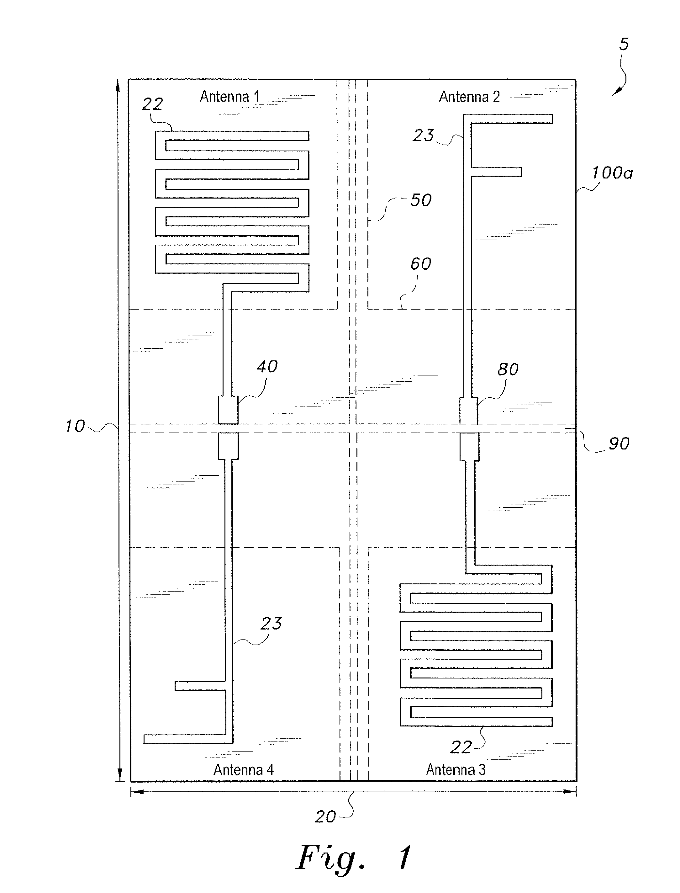
[0030]The high isolation multiband MIMO antenna system is exemplified by several different embodiments of MIMO antennas that are variations of microstrip antennas constructed of copper-clad strips on opposite faces of a dielectric substrate, such as a printed circuit board. The antennas are dimensioned and configured to fit within the housing of a handheld MIMO device, such as a mobile or portable radio or cellular telephone. Each embodiment is configured for communication on at least two different frequency bands, with each band having multiple transmit / receive antennas for MIMO wireless communication.

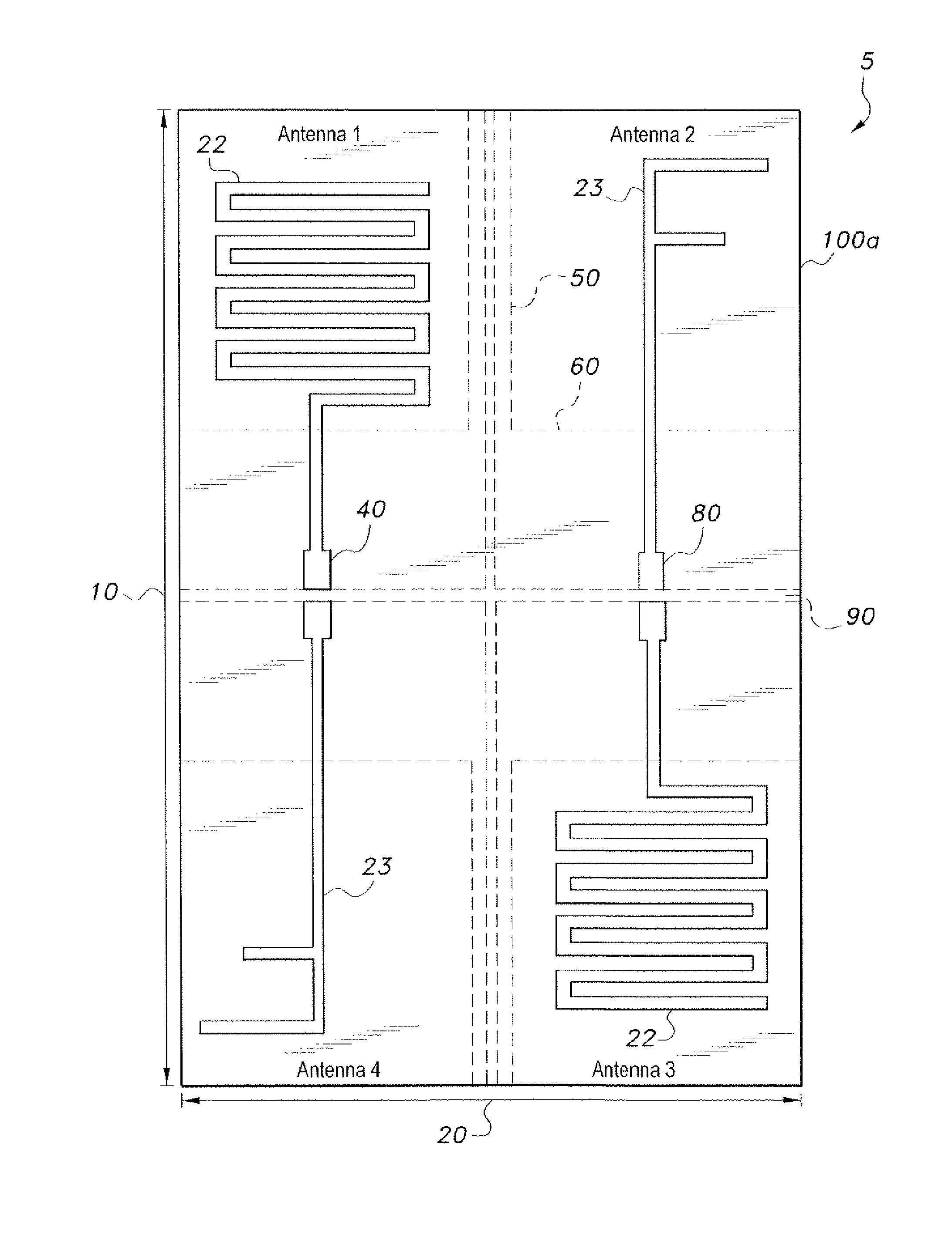
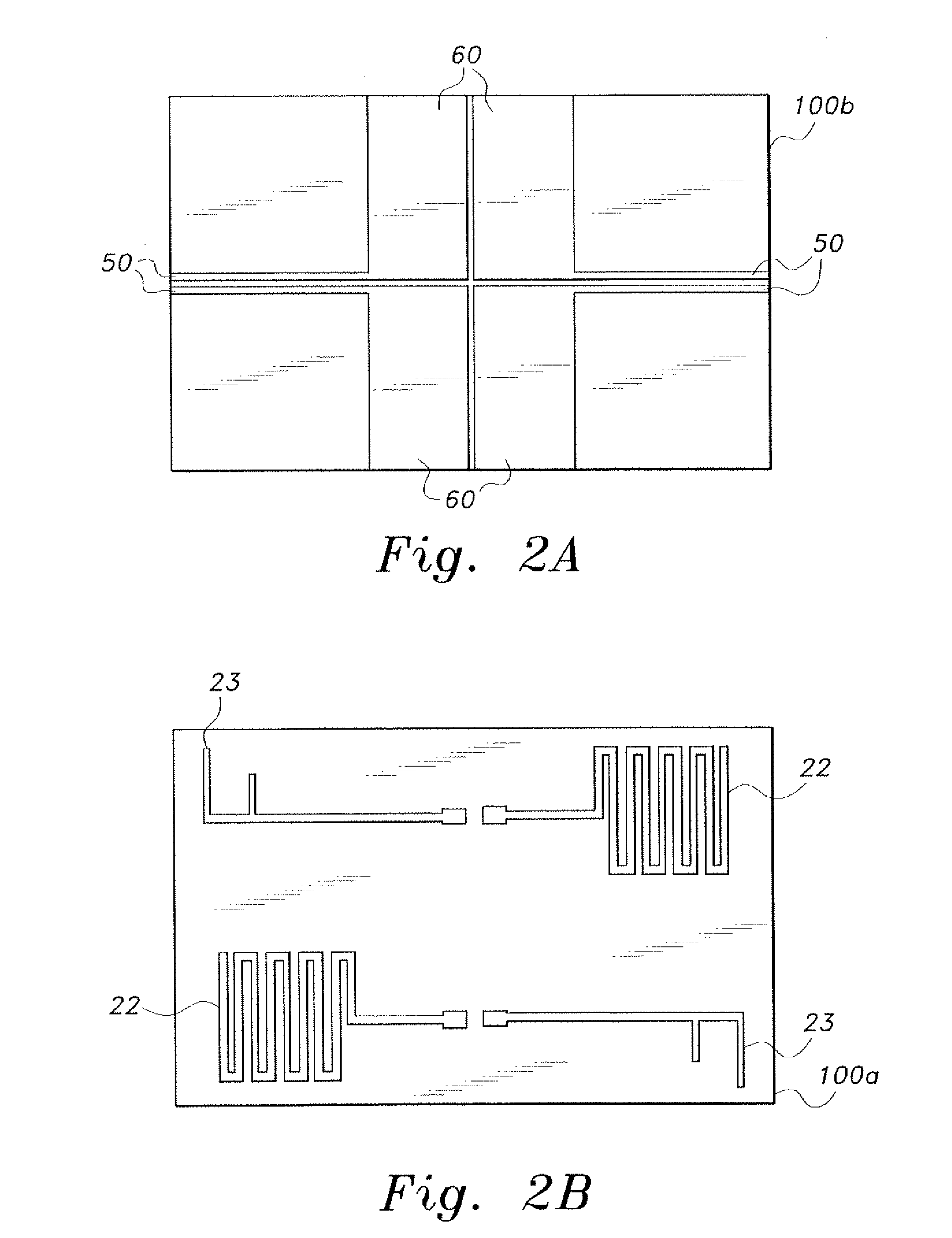
[0031]FIG. 1 shows an exemplary high isolation multiband MIMO antenna system 5 having four elements. The antennas of the system are printed on the top face 100a of a dielectric material substrate (sometimes referred to herein as an antenna board). The thickness of the substrate is preferably 0.8 mm, but other thicknesses can be used given that the thicknesses and lengths of the antenn...


PUM


Abstract

The high isolation multiband MIMO antenna system is a multi-band dual and quad antenna for multiple-input-multiple-output (MIMO) antenna systems. Element and ground plane geometries that can cover a wide range of frequency bands (780 MHz-5850 MHz) are based on the varying some simple geometrical lengths and widths of the elements and ground planes. The MIMO antenna systems can be used for next generation cellular and wireless MIMO communication systems. Several isolation enhancement schemes increase the isolation between adjacent antenna elements. Any combination of the isolation and MIMO antenna system geometries can be created to support different wireless system standards. The novel MIMO antenna systems are disposed within a dielectric substrate area of 50×100 mm2.

Description

BACKGROUND OF THE INVENTION[0001]1. Field of the Invention[0002]The present invention relates to antennas for multiple-input multiple-output (MIMO) wireless communications, particularly of the microstrip antenna type used, e.g., in handsets for mobile or cellular telephones, and more particularly to a high isolation multiband MIMO antenna system.[0003]2. Description of the Related Art[0004]The next generation of wireless systems will be capable of providing high throughputs, broader bandwidths, and better interference mitigation, thus providing multimedia services with peak data rates of more than 150 Mbps in the downlink and 50 Mbps in the uplinks. One of the key enabling technologies in such systems is the utilization of multiple-input-multiple-output (MIMO) antenna systems.[0005]MIMO antenna systems have a group of antennas in the transmitter and receiver terminals of the wireless system. This will allow the communication system to achieve higher data rates, and thus provide bett...

Claims


Application Information

Patent Timeline
Patent Type & Authority Applications(United States)
IPC IPC(8): H01Q1/38H01Q9/04H01Q5/10
CPCH01Q1/38H01Q21/28H01Q9/065H01Q1/521
Inventor SHARAWI, MOHAMMAD S.
Owner KING FAHD UNIVERSITY OF PETROLEUM AND MINERALS
Why Eureka
Eureka Blog
Learn More