
Method, TV set for displaying 3D image and glasses

Active Publication Date: 2012-05-17
HISENSE HIVIEW TECH CO LTD +1
View PDF5 Cites 4 Cited by
  • Summary
  • Abstract
  • Description
  • Claims
  • Application Information

AI Technical Summary

Benefits of technology

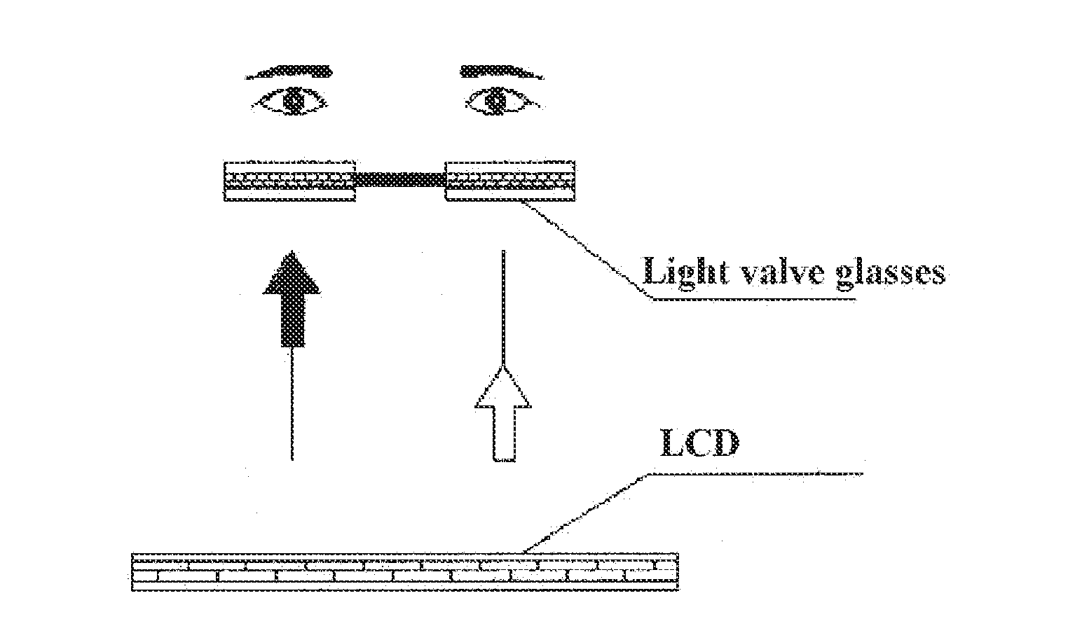
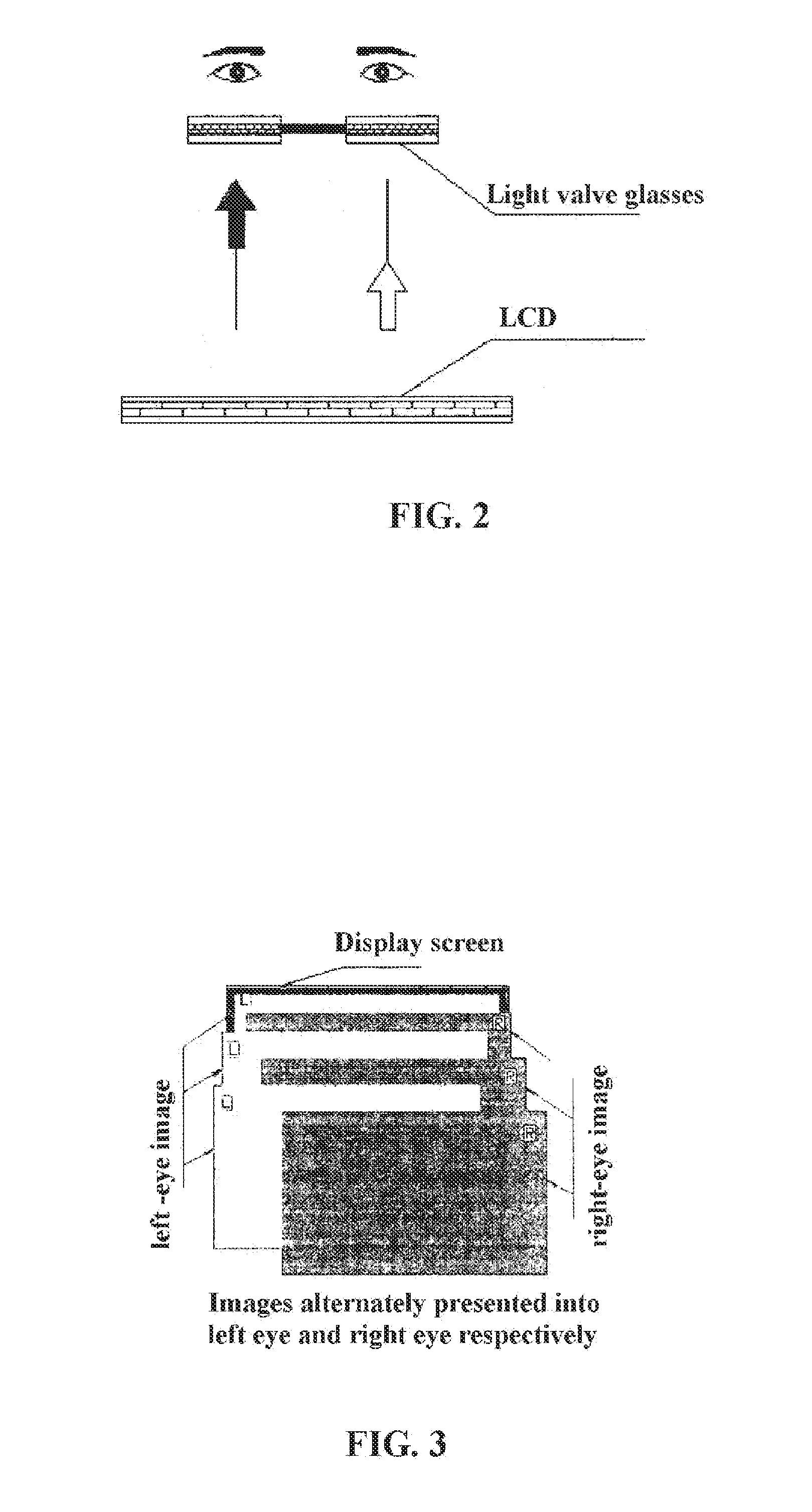
[0006]The present invention provides a method and a television set for displaying a 3d video as well as glasses, to solve the problem of crosstalk between the left-eye image and the right-eye image for LCD displays and to lower the overall implementation cost.
[0046]As compared with the prior art, the present invention may bring the following advantages.
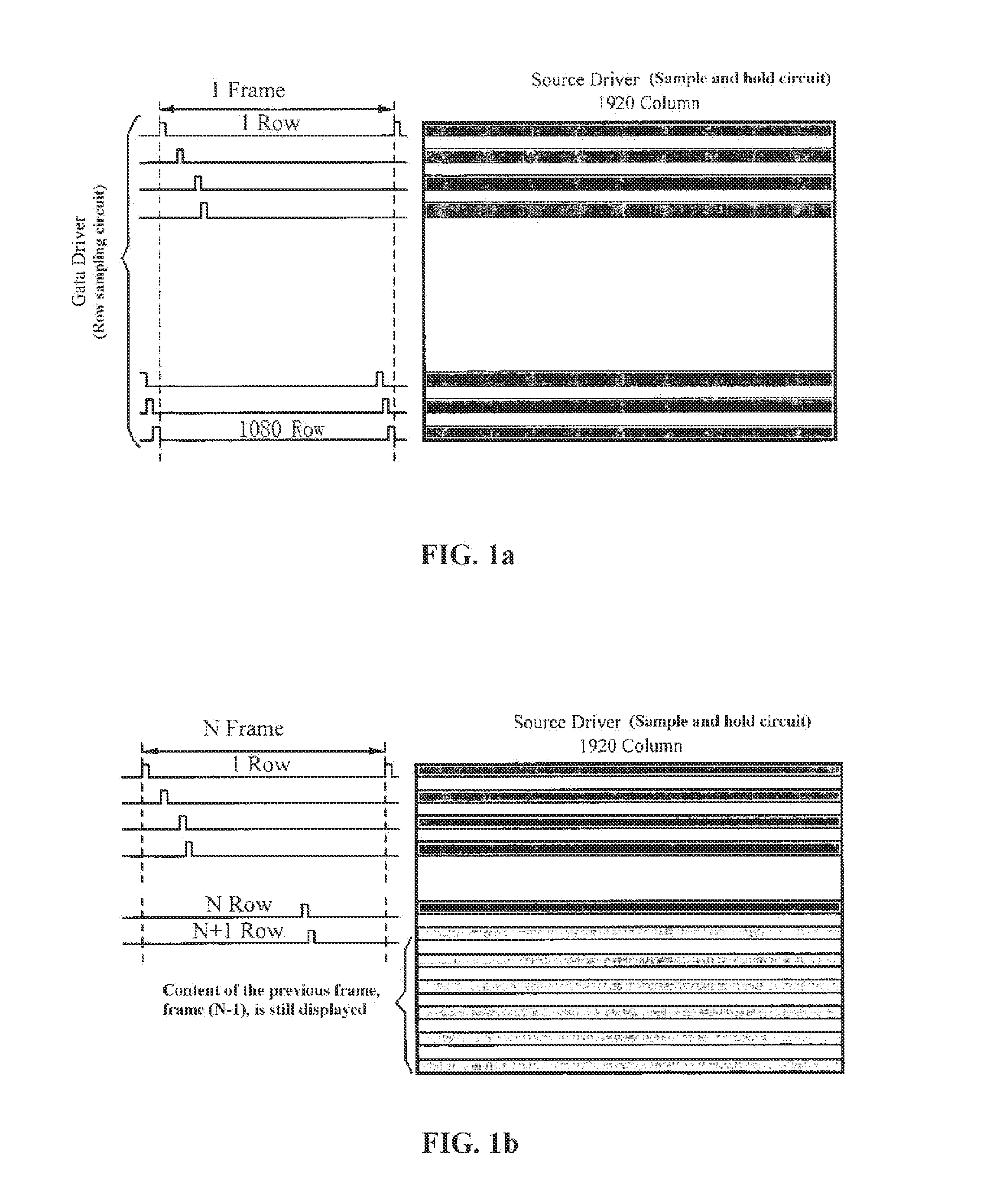
[0047]In one aspect, the problem of crosstalk between the left-eye image and the right-eye image is solved. Persistence of the last image in the current image due to the displaying mechanism of LCDs is unacceptable for 3D display, because the resulted crosstalk between the left-eye image and the right-eye image can significantly degrade the perception of 3D, or even make it impossible. The embodiments of the present invention can solve this problem. When the frame with crosstalk is displayed, which does have a content, yet nothing is shown except a black frame because the backlight is off; hence, the crosstalk is eliminated.
[0048]In another aspect, power consumption of the backlight source is reduced. According to an embodiment of the present invention, power consumption is nearly zero during the off period of the LED source. The LED control signal has a duty cycle of 50%, reducing the power consumption by nearly 50%.
[0049]In yet another aspect, the overall cost is low. As compared with other 3D display solutions, the embodiments of the present invention do not require expensive optical screens or optical retarders, thus simplifying the technology and largely lowering the overall cost.

Problems solved by technology

Disadvantages of the referring method include low resolution, and high cost of the 3D grating.
Disadvantages of the polarization-based method include high processing difficulty of the polarizing retarder, high cost and complex technology requirements of film attachment.

Method used


Image

  • Method, TV set for displaying 3D image and glasses
  • Method, TV set for displaying 3D image and glasses
  • Method, TV set for displaying 3D image and glasses

Examples


first embodiment

[0065] performing frequency multiplication on 3d video signal which is time multiplexed, and controlling LED backlight

[0066]The method for displaying a 3d video according to the first embodiment includes: receiving a 3d video signal, the 3d video signal including a frame of a left-eye signal and a frame of a right-eye signal that are consecutive; performing frequency multiplication on the 3d video signal, to obtain n consecutive frames of the left-eye signal and n consecutive frames of the right-eye signal, with n being the number by which a frequency is multiplied and equal to or greater than 2; and driving, by light-emitting diode (LED) driving signals, a panel to display the n consecutive frames of the left-eye signal and the n consecutive frames of the right-eye signal,

[0067]wherein among the n consecutive frames of the left-eye signal, the first frame of the left-eye signal corresponds to an LED driving signal which is off, and the nth frame of the left-eye signal corresponds t...

second embodiment

[0092] performing frequency multiplication on time multiplexed 3d video signal, and inserting black frame.

[0093]The method for displaying 3d video according to the second embodiment includes: receiving a 3d video signals, the 3d video signal including a frame of a left-eye signal and a frame of a right-eye signal; inserting a black frame to the 3d video signal, and performing frequency multiplication on the 3d video signal, to generate n consecutive frames of the left-eye signal and n consecutive frames of the right-eye signal including the black frame, with n being the number by which a frequency is multiplied and equal to or greater than 2, wherein among the n consecutive frames of the left-eye signal, the first frame of the left-eye signal is a black frame, and the nth frame of the left-eye signal is a non-black frame; and, among the n consecutive frames of the right-eye signal, the first frame of the right-eye signal is a black frame, and the nth frame of the right-eye signal is...

third embodiment

[0116]Reference is made to FIG. 8, which illustrates a timing diagram of a time multiplexed 3d video signal, an LED driving signal and left-eye and right-eye signals according to the present invention. As compared with FIG. 7, the

[0117]LED driving signal is on in the Rn″th, the Ln″th, the (Rn+1)″th, and the (Ln+1)″th frames, and is off in the Rn′th, the Ln′th, the (Rn+1)′th, and the (Ln+1)′th frames. In the signal received by the left eye, the proceeding part is the image content, and due to the black frame, the latter part is dark because the LED is off. The case with the signal received by the right eye is similar.

[0118]As compared with the prior art, the method for 3D display provided by the third embodiment of the present invention may bring at least the following advantages.

[0119]In one aspect, the problem of crosstalk between the left-eye image and the right-eye image is solved. Persistence of the last image in the current image due to the displaying mechanism of LCDs is unacc...


PUM


Abstract

A method for displaying 3D image is provided in the present invention. The method includes: 3D image signals, which comprise consecutive one frame of left-eye signal and one frame of right-eye signal, are received; the 3D image signals are processed by frequency multiplication, and n consecutive frames of left-eye signals and n consecutive frames of right-eye signals are obtained, n being the times number of the frequency multiplication and equal to or greater than 2; light-emitting diode (LED) driving signals drive the LED to display the n consecutive frames of left-eye signals and the n consecutive frames of right-eye signals; in the n consecutive frames of left-eye signals, the first frame of left-eye signal corresponds to an LED driving signal which is off, the nth frame of left-eye signal corresponds to an LED driving signal which is on, and in the n consecutive frames of right-eye signals, the first frame of right-eye signal corresponds to an LED driving signal which is off, the nth frame of right-eye signal corresponds to an LED driving signal which is on. The present invention also provides a TV set for displaying 3D image and a pair of glasses for viewing 3D image. By the present invention, the problem of crosstalk between leftimage and rightimage is solved, and backlight sources energy consumption and complete apparatus cost are reduced.

Description

[0001]This application is a national stage application of PCT / CN2010 / 070705 filed on Feb. 22, 2010, which claims the benefit of Chinese patent application No.200910170876.X titled “Method and Television Set for Displaying 3D (Three dimension) Video and Glasses” and filed with the State Intellectual Property Office on Sep. 11, 2009. Both the international application and the Chinese application are incorporated herein by reference in their entireties.FIELD OF THE INVENTION[0002]The present invention relates to the field of three-dimensional technologies, and in more particular to a method and a television set for displaying a 3d video as well as glasses.BACKGROUND OF THE INVENTION[0003]The principle of 3D display technologies is to use optical or circuit processing to present two slightly offset images to the left and right eye respectively, without mutual interference. Both of the offset images are then combined in the cerebral cortex to give the perception of 3D. Many methods are a...

Claims


Application Information

Patent Timeline
IPC IPC(8): H04N13/04
CPCG02B27/2264G09G3/003G09G3/3406H04N13/0497G09G2330/021G09G2340/0435H04N13/0438G09G2310/08G02B30/24H04N13/341H04N13/398
Inventor LIU, WEIDONGGAO, WEISONGLI, CHUNPUSHANG, JUNHUIDONG, YUZHENMIAO, YONGPING
Owner HISENSE HIVIEW TECH CO LTD
Learn More