
Method for improving 3 dimensional effect and reducing visual fatigue and apparatus enabling the same

a three-dimensional effect and visual fatigue technology, applied in the field of three-dimensional (3d) photographing, can solve the problems of viewer dizziness and failure to give the viewer the correct 3d image, and achieve the effect of less visual fatigue and greater 3d

Inactive Publication Date: 2012-05-17
SAMSUNG ELECTRONICS CO LTD +1
View PDF30 Cites 30 Cited by
  • Summary
  • Abstract
  • Description
  • Claims
  • Application Information

AI Technical Summary

Benefits of technology

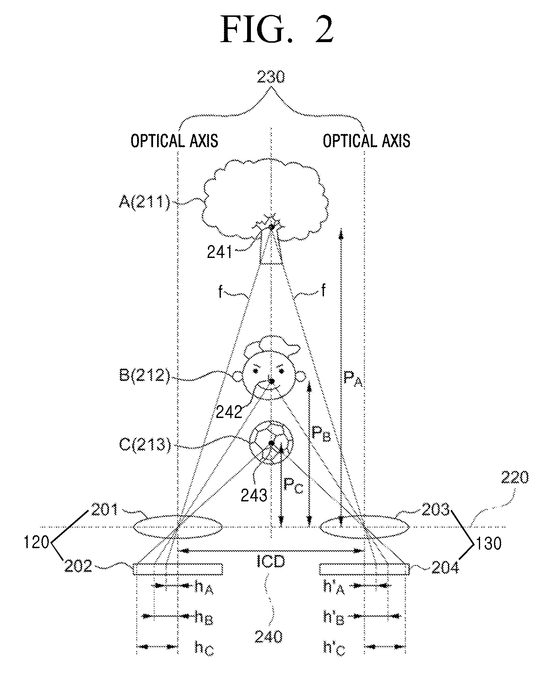
The present invention provides a method and apparatus for improving the 3D effect of a 3D image collected by a 3D photographing apparatus and reducing visual fatigue for viewing the 3D image. This is achieved by acquiring feature points of a left-eye and right-eye image, detecting a disparity between the left- and right-eye images, controlling a distance between the left- and right-eye lenses so that the disparity between the left- and right-eye images becomes a previously-set reference disparity, and shifting at least one of the left- and right-eye images so that a convergence point is placed on a specific object located within the left- and right-eye images. This method and apparatus can provide images with less visual fatigue and greater 3D effect.

Problems solved by technology

That is, an excessively long distance between left- and right-eye images will create an excessively deep 3D photo or video effect, thereby causing dizziness to the viewer.
Conversely, too short of a distance between left- and right-eye images creates a compromised 3D effect, which fail to give the viewer the correct 3D image.

Method used


Image

  • Method for improving 3 dimensional effect and reducing visual fatigue and apparatus enabling the same
  • Method for improving 3 dimensional effect and reducing visual fatigue and apparatus enabling the same
  • Method for improving 3 dimensional effect and reducing visual fatigue and apparatus enabling the same

Examples


Embodiment Construction

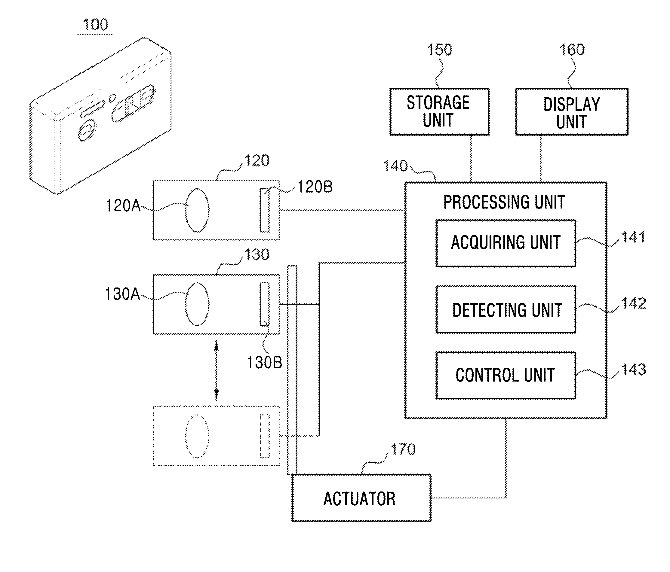
[0028]Embodiments of the present invention will be described in detail with reference to the accompanying drawings. In the following description, specific details such as detailed configuration and components are merely provided to assist the overall understanding of embodiments of the present invention. Therefore, it should be apparent to those skilled in the art that various changes and modifications of the embodiments described herein can be made without departing from the scope and spirit of the invention. Throughout the drawings, the same drawing reference numerals will be understood to refer to the same elements, features and structures. In addition, descriptions of well-known functions and constructions are omitted for the sake of clarity and conciseness. FIG. 1 illustrates a 3D photographing apparatus 100 according to the present invention.

[0029]Referring to FIG. 1, the 3D photographing apparatus 100 includes a left-eye lens unit 120, a right-eye lens unit 130, a processing ...


PUM


Abstract

A method and an apparatus for improving three dimensional (3D) effect of a 3D image collected by a 3D photographing apparatus, and reducing visual fatigue, are provided. A feature point of a left-eye image entering through a left-eye lens and of a right-eye image entering through a right-eye lens is acquired, a disparity between the left- and right-eye images is detected, a distance between the left- and right-eye lenses is controlled so that the disparity between the left- and right-eye images becomes a previously-set reference disparity, and at least one of the left- and right-eye images is shifted so that a convergence point is placed on an object located within the left- and right-eye images.

Description

PRIORITY[0001]This application claims priority under 35 U.S.C. §119(a) to Korean Patent Application No. 10-2010-0112687, filed on Nov. 12, 2010 in the Korean Intellectual Property Office, the contents of which are incorporated herein by reference.BACKGROUND OF THE INVENTION[0002]1. Field of the Invention[0003]The present invention relates generally to three dimensional (3D) photographing, and more particularly, to a method for improving the 3D effect of a 3D image collected by a 3D photographing apparatus and reducing visual fatigue for viewing the 3D image, and an apparatus enabling the same.[0004]2. Description of the Related Art[0005]The 3D imaging technology can be used in a variety of applications including, but not limited to, information and communication, broadcasting, medical science, education, training, military, games, animation, virtual reality, Computer-Aided Design (CAD), and industrial technology.[0006]A person may perceive depth based on varying eye lens thicknesses...

Claims


Application Information

Patent Timeline
Patent Type & Authority Applications(United States)
IPC IPC(8): H04N13/02H04N13/239
CPCH04N2013/0081H04N13/0239H04N13/239H04N13/144
Inventor YOON, KUK-JINKIMURA, MAKOTOLEE, JIN-KYUNGTAKANE, YASUOKIM, TAE-KYUNGCHOI, HYUN-SEOKJEONG, TAEK-SEONGMOON, KYOUNG-HWANMASAHIRO, TAKASHIMA
Owner SAMSUNG ELECTRONICS CO LTD
Learn More