
Film formation apparatus and film formation method

Inactive Publication Date: 2012-05-10
CANON KK
View PDF6 Cites 7 Cited by
  • Summary
  • Abstract
  • Description
  • Claims
  • Application Information

AI Technical Summary

Benefits of technology

[0013]The present invention has been made to solve the problems described above, and an object of the present invention is to provide a film formation apparatus and a film formation method which may control with accuracy the thickness of a thin film formed on a film formation object without lowering the productivity.
[0014]According to the present invention, it is possible to provide the film formation apparatus and the film formation method which may control with accuracy the thickness of the thin film formed on the film formation object without lowering the productivity.

Problems solved by technology

Therefore, it is difficult to control the thickness of the film on the film formation object with accuracy for a long period of time.
Japanese Patent Application Laid-Open No. 2008-122200 discloses a method of making smaller a film thickness value error which presents a problem in controlling the thickness of a film on a film formation object.
However, when the calibration step is performed between film formation steps, the film is not formed on the film formation object during that period, and thus, there is a problem that the productivity is lowered.
On the other hand, in Japanese Patent Application Laid-Open No. 2004-091919, the film thickness sensor is fixed at the waiting position of the film formation source (the position at which the film is not formed on the film formation object), and thus, the film thickness sensor cannot monitor the amount of the film forming material released from the film formation source during the film formation step.
Therefore, even if the quartz oscillator for calibration disclosed in Japanese Patent Application Laid-Open No. 2008-122200 is provided in the thin film formation apparatus disclosed in Japanese Patent Application Laid-Open No. 2004-091919, it is impossible to carry out the calibration step during the film formation step.

Method used


Image

  • Film formation apparatus and film formation method
  • Film formation apparatus and film formation method
  • Film formation apparatus and film formation method

Examples


example

Example 1

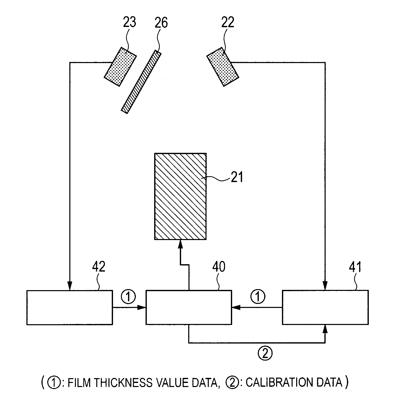
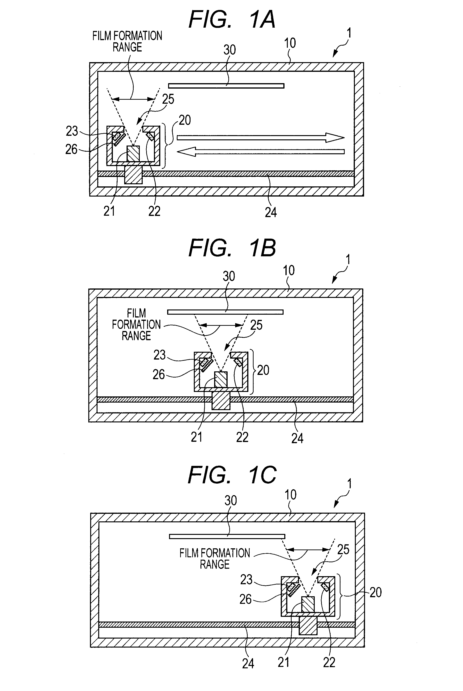
[0061]The film formation apparatus illustrated in FIGS. 1A to 1C was used to form the film of the film forming material on the substrate.

[0062]In this example, the film was formed by reciprocating once the film formation source unit 20 with the transport distance being 1,000 mm and with the transport speed being 20 mm / s. The length in a longitudinal direction of the substrate (film formation object 30) was 500 mm.

[0063]Further, in this example, the heating temperature of the film formation source 21 was adjusted so that the thickness of the thin film of the film forming material formed on the substrate (film formation object 30) was 100 nm.

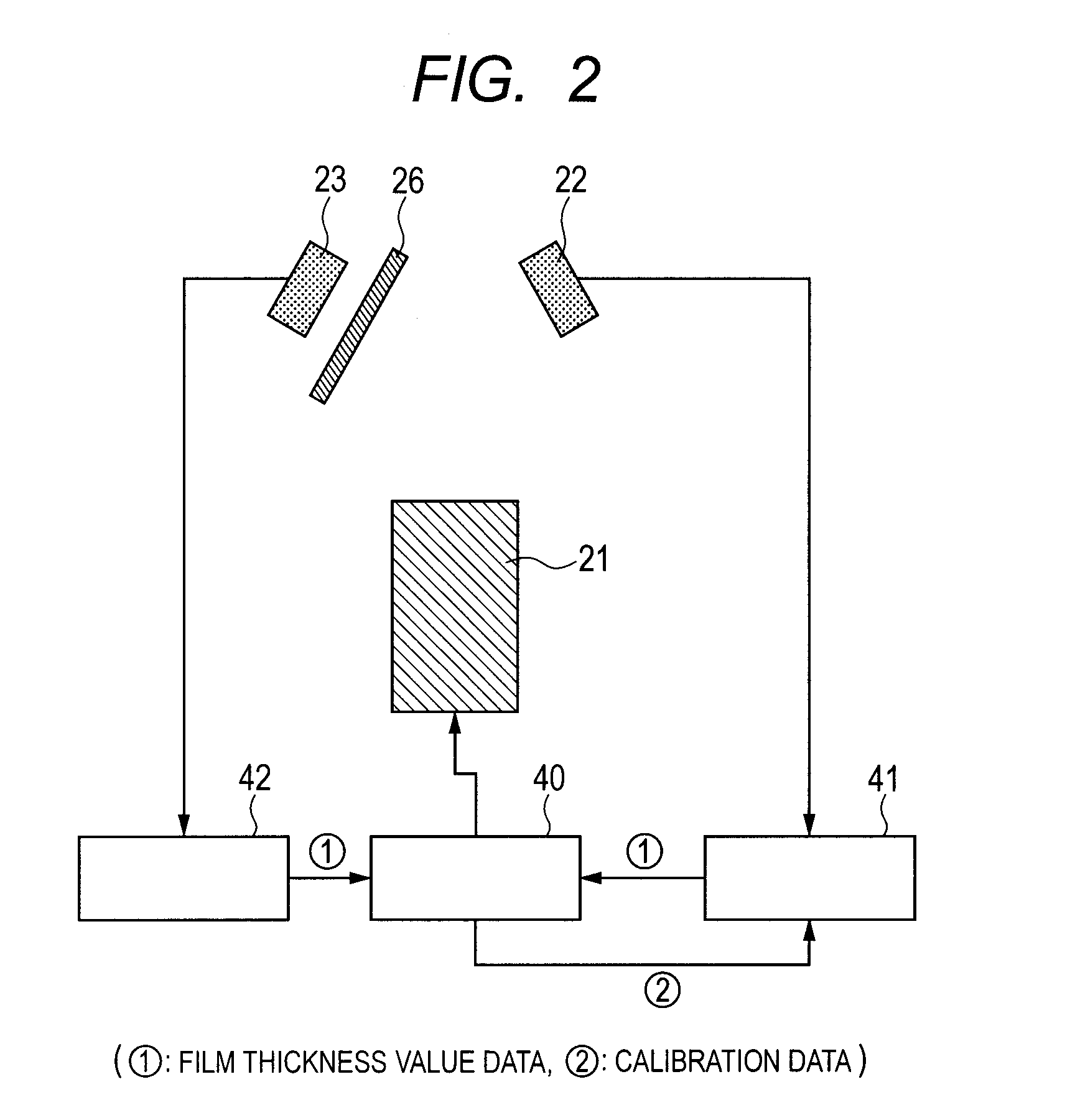
[0064]Further, in this example, as the quartz oscillator 22 for measurement and the quartz oscillator 23 for calibration, 6 MHz quartz oscillators having gold electrodes and manufactured by INFICON were used.

[0065]First, the preliminary step of the film formation was performed.

[0066]In this preliminary step, first, the substrate (film for...


PUM


Abstract

Provided are a film formation apparatus and a film formation method which may control with accuracy the thickness of a thin film formed on the film formation object. A film formation apparatus includes a moving part (film formation source unit) for moving a film formation source between a predetermined film formation waiting position and a predetermined film forming position is provided, and the moving part holds a quartz oscillator for measurement and a quartz oscillator for calibration so that their relative positions with respect to the film formation source are maintained. And a calibration step for calibrating a monitored value of the quartz oscillator for measurement, using a monitored value of the quartz oscillator for calibration, is performed in a middle of the film forming step of forming the film on the film formation object.

Description

BACKGROUND OF THE INVENTION[0001]1. Field of the Invention[0002]The present invention relates to a film formation apparatus and a film formation method which uses the film formation apparatus.[0003]2. Description of the Related Art[0004]Conventionally, when a thin film is formed on a film formation object such as a substrate by evaporation, sputtering, or the like, in order to control the thickness of the thin film to be formed, a quartz oscillator is placed in a film formation chamber. When a quartz oscillator is placed in the film formation chamber, in forming the thin film, a film forming material forming the thin film is deposited both on the quartz oscillator and on the film formation object. Here, as the film forming material is deposited on the quartz oscillator, the resonance frequency of the quartz oscillator changes according to the amount of the film forming material deposited thereon. Using this phenomenon, the thickness of the film of the film forming material deposited...

Claims


Application Information

Patent Timeline
IPC IPC(8): C23C16/52C23C16/455
CPCC23C14/546C23C14/24C23C14/54C23C16/46C23C16/52
Inventor NAKAGAWA, YOSHIYUKINAKANO, SHINGOFUKUDA, NAOTO
Owner CANON KK
Learn More