
Control system and control method of a solar power supply

a solar power supply and control system technology, applied in the direction of battery/fuel cell control arrangement, secondary cell servicing/maintenance, light to electrical conversion, etc., to achieve the effect of improving maximizing the utilization of solar energy

Active Publication Date: 2012-05-10
BYD CO LTD
View PDF6 Cites 45 Cited by
  • Summary
  • Abstract
  • Description
  • Claims
  • Application Information

AI Technical Summary

Benefits of technology

[0029]When the vehicle is running or parked, the solar power supply may provide power to the vehicle, realizing the maximum utilization of the solar energy and improving the utilization of the solar energy.

Problems solved by technology

The disadvantage is that: when the vehicle is parked, the solar energy is not used for the vehicle, not realizing maximum utilization of the solar energy to charge the vehicle.

Method used


Image

  • Control system and control method of a solar power supply
  • Control system and control method of a solar power supply
  • Control system and control method of a solar power supply

Examples


Embodiment Construction

[0034]Reference will be made in detail to embodiments of the present invention. The embodiments described herein with reference to drawings are explanatory, illustrative, and used to generally understand the present invention. The embodiments shall not be construed to limit the present invention. The same or similar elements and the elements having same or similar functions are denoted by like reference numerals throughout the descriptions.

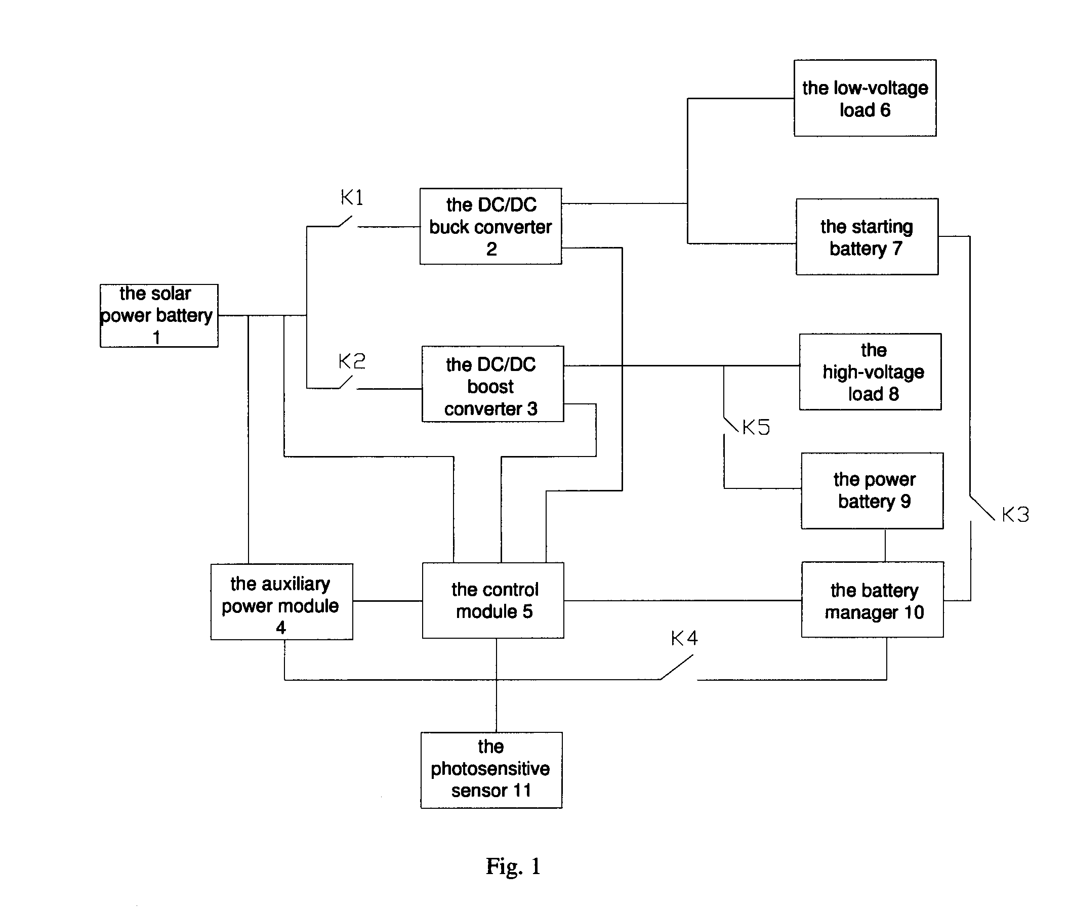
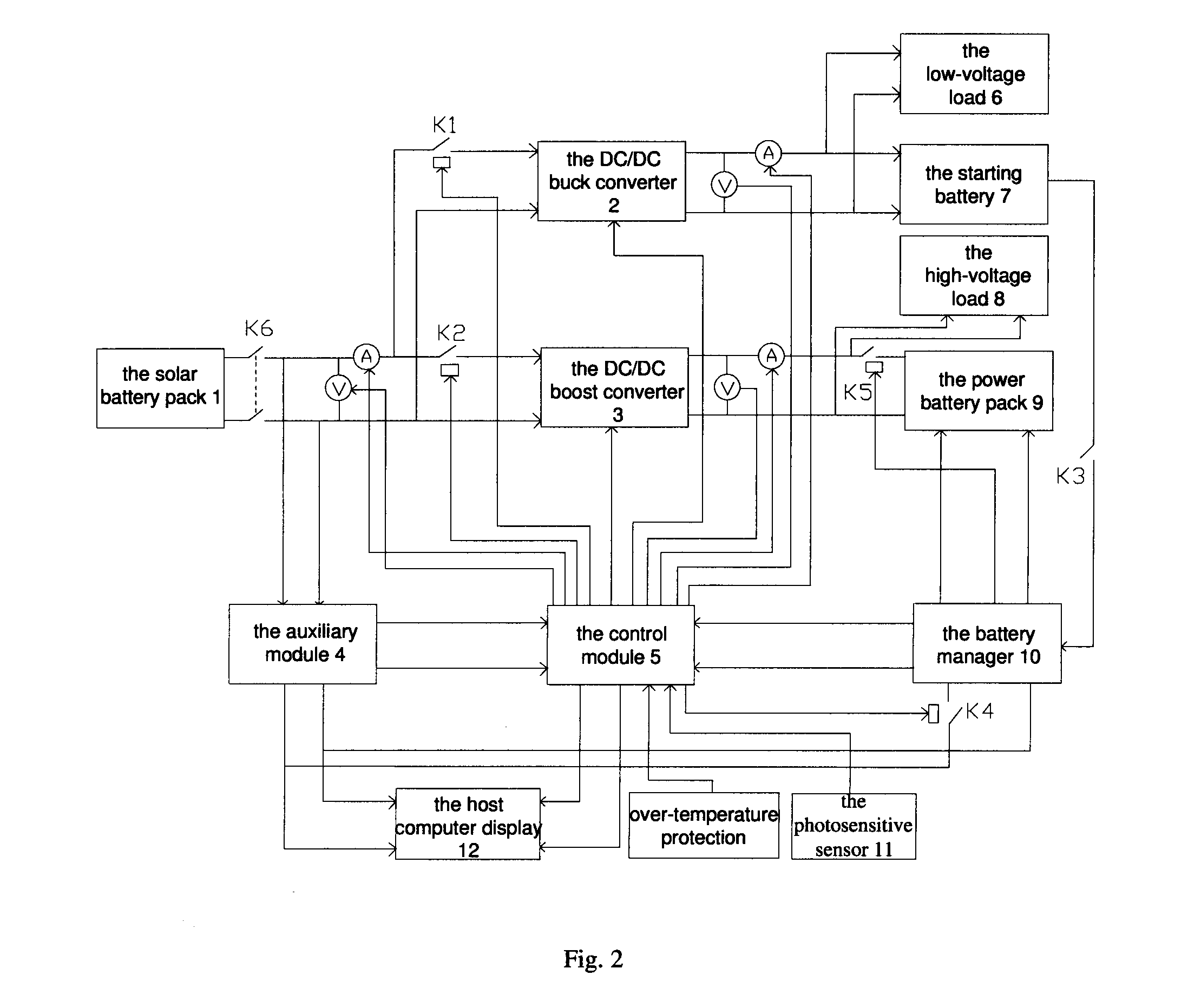
[0035]As shown in FIG. 1, the schematic diagram illustrates a control system of a solar power supply according to an embodiment of the present invention. The control system of the solar power supply comprises a solar battery pack 1; a DC / DC buck converter 2; a DC / DC boost converter 3; a control module 5; a low-voltage load 6; a starting battery 7; a high-voltage load 8; a power battery pack 9; an auxiliary power module 4; a photosensitive sensor 11; a main contactor K5; a first switch K1; a second switch K2; a third switch K3; and a fourth switch ...


PUM


Abstract

A control system of a solar power supply for a vehicle is provided. The control system includes a solar battery pack and a control module. The solar battery is connected to an auxiliary power module, the control module, a DC / DC buck converter via a first switch, and connected to a DC / DC boost converter via a second switch. The DC / DC buck converter is connected to a low-voltage load, a starting battery and the control module. The DC / DC boost converter is connected to a high-voltage load, the control module, a power battery pack via a main contactor.

Description

CROSS-REFERENCE TO RELATED APPLICATIONS[0001]The present application claims priority to and benefits of Chinese Patent Application No. 201010296994.8 filed with State Intellectual Property Office of China on Sep. 30, 2010, the entirety of which is hereby incorporated by reference.BACKGROUND[0002]1. Technical Field[0003]The present invention relates to control of a power supply for a vehicle, more particularly to a control system and control method of a solar power supply.[0004]2. Description of the Related Art[0005]To solve the problem of energy shortage and more and more severe environmental pollution, the new energy (including electric energy and solar energy) are utilized in vehicles. The utilization of the solar energy to charge the vehicle, not only reduces the environmental pollution and protects the environment, but also, prolongs the driving range of the vehicle.[0006]At present, the application of the solar energy to electric vehicles is to provide power to the battery afte...

Claims


Application Information

Patent Timeline
IPC IPC(8): H01M10/46
CPCB60L3/0046Y02T10/92B60L8/003B60L11/1812B60L11/1868B60L2210/12B60L2210/14B60L2240/545B60L2240/547B60L2240/549B60L2250/10B60L2250/16H02J7/35Y02T10/7005Y02T10/7066Y02T10/7083Y02T10/7225Y02T10/7233Y02T90/127Y02T90/14B60L3/0069Y02T10/7072B60L53/22B60L58/20Y02T10/70Y02T10/72Y02T90/12
Inventor XU, YANGLIANG, SHULINZHANG, JIANHUA
Owner BYD CO LTD
Learn More