
System and Method For A Light Bulb Fixture with Sensor Switch and Its Operation and Method for operating the same

a technology of light bulb fixture and sensor switch, which is applied in the direction of transit tube circuit elements, structural circuit elements, cathode-ray/electron beam tube circuit elements, etc., can solve the problems of not being available, and achieve the effect of convenient replacement of light bulbs and convenient measurement of peopl

Inactive Publication Date: 2012-05-10
LEE JASOPIN
View PDF2 Cites 15 Cited by
  • Summary
  • Abstract
  • Description
  • Claims
  • Application Information

AI Technical Summary

Benefits of technology

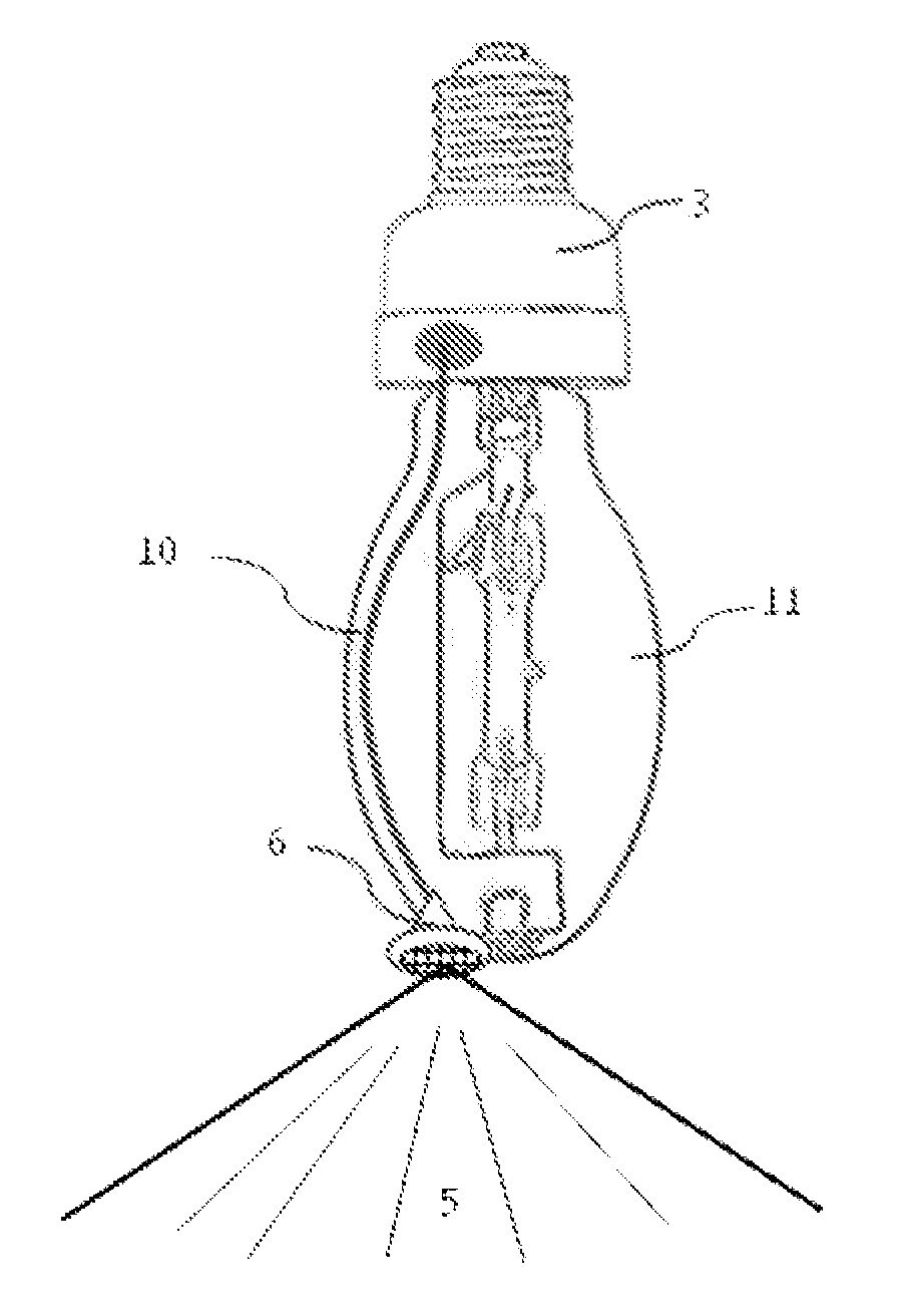
"The patent describes a system and method for integrating a sensor into a light bulb and fixture hardware. The sensor can detect the presence of people or moving objects in a given area, and the light bulb will switch off after a set period of time if no activity is detected. The sensor can be made with various technologies such as infrared, ultrasonic, microwave, or laser. The system also includes a control circuitry housing that can be fitted into the light bulb hardware and is decorative in shape. The sensor unit can be easily detached and attached for replacement and assembly. The technical effects of this patent include energy efficiency, convenience, and improved safety."

Problems solved by technology

However, they are not meant for managing interior lighting or for saving energy, nor are they available for said purposes.

Method used


Image

  • System and Method For A Light Bulb Fixture with Sensor Switch and Its Operation and Method for operating the same
  • System and Method For A Light Bulb Fixture with Sensor Switch and Its Operation and Method for operating the same
  • System and Method For A Light Bulb Fixture with Sensor Switch and Its Operation and Method for operating the same

Examples


Embodiment Construction

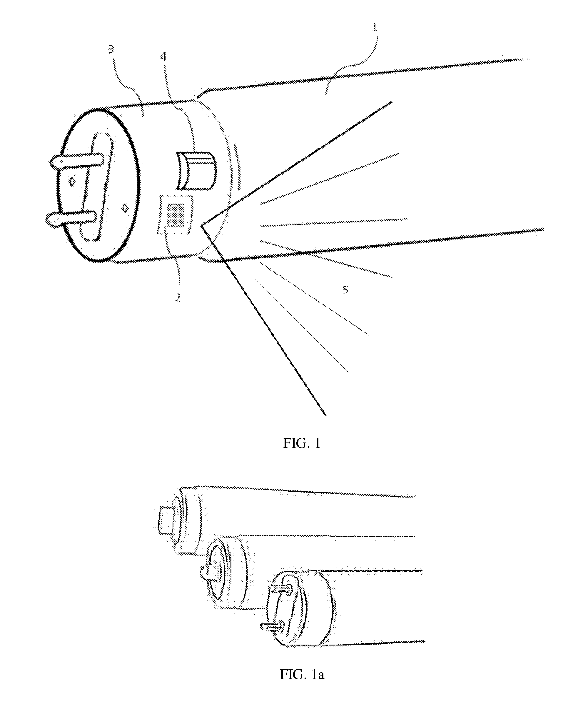
[0022]FIG. 1 shows one drawing of a fluorescent light bulb 1 with an integrated occupancy sensor and light meter 2 at the end of a long fluorescent light bulb. The hardware at one end of the light bulb has been extended toward the light tube to house the sensor and circuitry, and the glass tube light section is reduced slightly to keep the light bulb total length unchanged. Although the technology will also enable power saving of shorter light bulbs, the main purpose of this invention is to conserve the power consumption of high power (4 ft and 8 ft or longer) fluorescent light bulbs. The housing 3 could be enlarged some to accommodate the sensor and switch circuitry, as long as it can still be plugged into the original light fixture socket. A sensor lens cover 4 is used to provide a wide-angle view sensing direction 5 and to seal the unit from dust.

[0023]FIG. 1a shows one drawing of three light bulb connectors at the end of a long fluorescent light bulb. This invention can fit into...


PUM


Abstract

A system and method of light bulb and fixture comprising an occupancy sensor, a light meter, and an on / off circuit switch is used to manage the lighting use base on the sensing the presence of people and area lighting condition. The occupancy sensor, light meter, an on-off circuit switch, and a regulator are incorporated into the light bulb or fixture for easy replacement and no need of re-wiring or major fixture change.

Description

CROSS-REFERENCE TO RELATED APPLICATIONS[0001]U.S. Pat. No. 5,662,441September 1997Haslam et al.362 / 276U.S. Pat. No. 6,151,529 ANovember 2000Batko700 / 28U.S. Pat. No. RE37,135 EApril 2001Elwell315 / 154U.S. Pat. No. 6,566,882 B2May 2003Baldwin et al.324 / 418U.S. Pat. No. 6,583,573 B2June 2003Bierman315 / 419U.S. Pat. No. 6,798,341 B1September 2004Eckel et al.340 / 521U.S. Pat. No. 6,909,239 B2June 2005Gauna315 / 134U.S. Pat. No. 6,956,493 B1October 2005Youngblood340 / 693.9U.S. Pat. No. 7,005,802 B2February 2006Myron et al.315 / 56U.S. Pat. No. 2006 / 0181416 A1August 2006Chen340 / 545.2U.S. Pat. No. 7,122,976 B1October 2006Null et al.315 / 362U.S. Pat. No. 7,164,238 B2January 2007Kazanov et al.315 / 209U.S. Pat. No. 7,175,315 B2February 2007Eaton362 / 276U.S. Pat. No. 7,190,126 B1March 2007Paton315 / 308U.S. Pat. No. 7,327,254 B2February 2008Chen340 / 545.2U.S. Pat. No. 7,405,524 B2July 2008Null et al.315 / 308U.S. Pat. No. 7,585,087 B2September 2009Gagne et al362 / 221U.S. Pat. No. 7,626,339 B2December 2009Paton3...

Claims


Application Information

Patent Timeline
Patent Type & Authority Applications(United States)
IPC IPC(8): H01K1/62H05B37/02
CPCH05B37/0227H01J61/56H05B47/115Y02B20/40
Inventor LEE, JASOPIN
Owner LEE JASOPIN
Learn More