
Radio communication apparatus

a communication apparatus and radio technology, applied in the field of radio communication apparatus, can solve the problem of consuming power for a useless receiving process, and achieve the effect of easing the processing load of the communication apparatus (mobile station), effectively accomplishing adaptive modulation and coding, and alleviating the processing load

Active Publication Date: 2012-05-03
FUJITSU LTD
View PDF5 Cites 5 Cited by
  • Summary
  • Abstract
  • Description
  • Claims
  • Application Information

AI Technical Summary

Benefits of technology

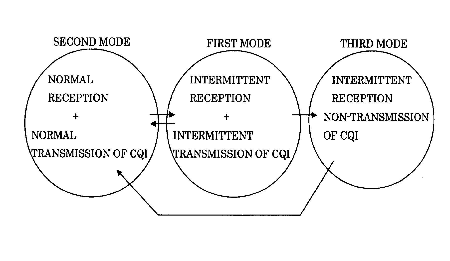
The present invention aims to reduce the processing load of a communication apparatus (mobile station) during data transmission utilizing shared channels. It proposes a solution for adaptive modulation and coding while alleviating the processing load. The invention provides a radio communication apparatus for receiving and transmitting data via a shared channel, which includes a receiving unit for intermittent reception and a transmitting unit for intermittent transmission of information that influences the transmitting method of the data. The receiving unit and transmitting unit can have different periods of intermittent operation. The invention also includes a control unit that can switch between modes for transmitting and receiving data, and can limit the period of data transmission to non-continuous periods. The technical effects of the invention include reducing processing load, improving data transmission efficiency, and enhancing user experience.

Problems solved by technology

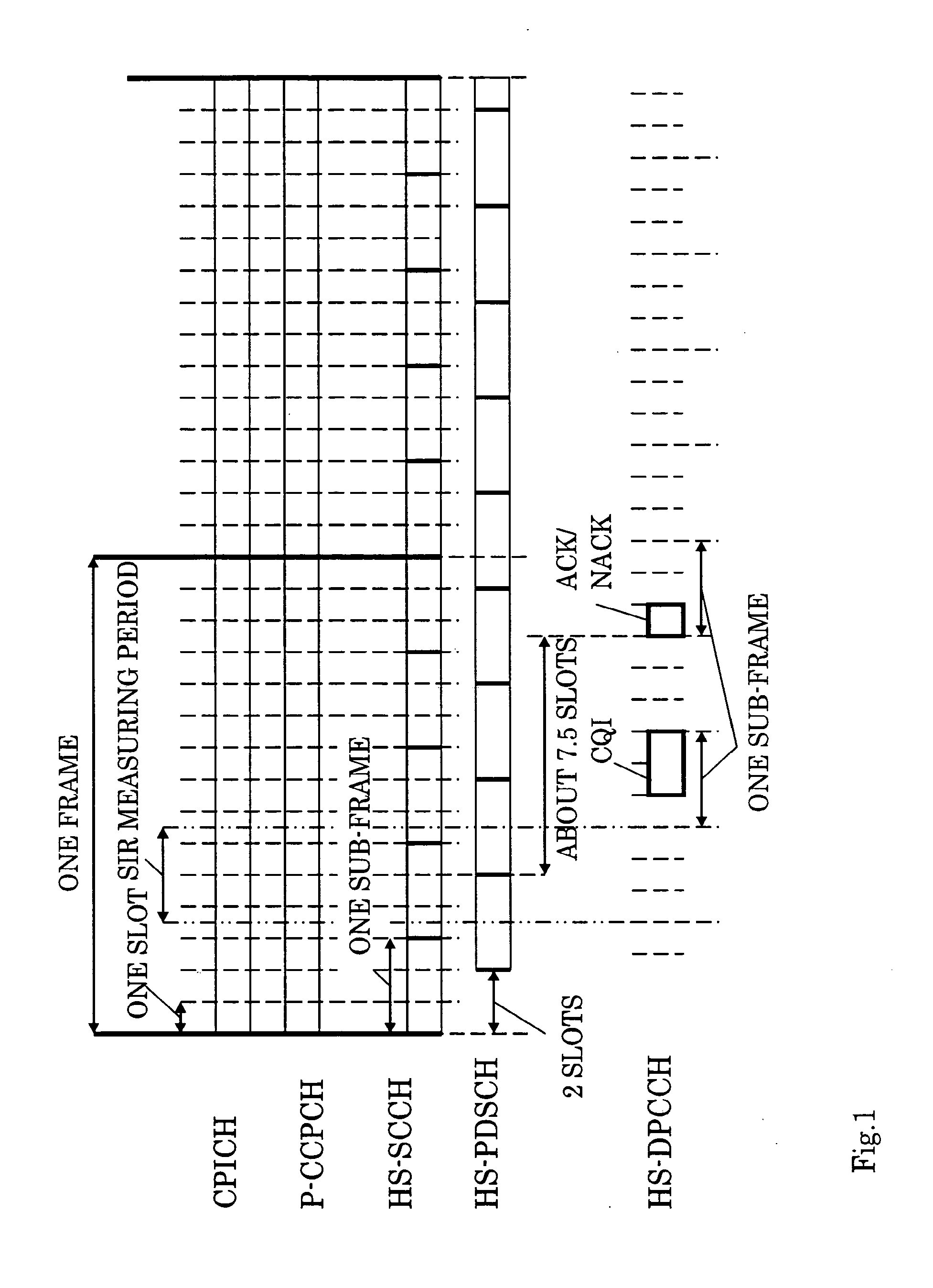
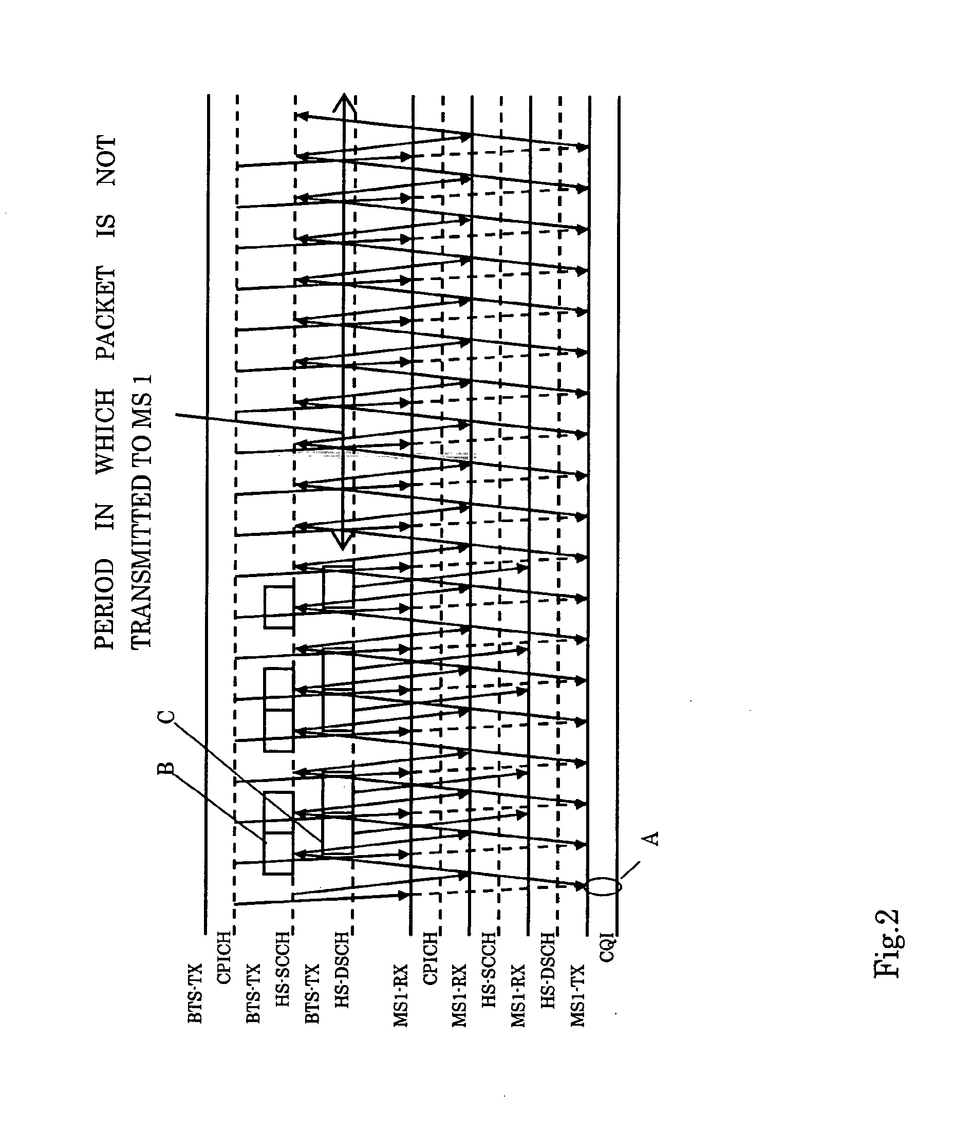
According to the background art explained above, application efficiency of channels can be improved by utilizing the shared channels, but since a receiving station receives the HS-SCCH with every sub-frame, if the data received not transmitted to its own station, it is a problem to be solved, from the viewpoint of the receiving station itself, that power is consumed for a useless receiving process.

Method used


Image

  • Radio communication apparatus
  • Radio communication apparatus
  • Radio communication apparatus

Examples


first embodiment

[a] Explanation of First Embodiment

[0066]In this embodiment, intermittent reception is accomplished to determine whether the data received via the shared channel is transmitted to its own station or not and the information influencing the transmission format of the data received via the shared channel is also accomplished a predetermined time before the timing of the intermittent reception.

[0067]Therefore, the processing load (power consumption) can be reduced by implementing the intermittent reception to determine whether the data received via the shared channel is transmitted to its own station or not and the transmission format of the data transmitted via the shared channel may be controlled adequately.

[0068]As explained previously, for data transmission utilizing the shared channel, a variety of communication apparatuses (for example, the radio communication apparatuses forming the radio LAN system or the like) may be used, but an example of the radio communication apparatus cor...


PUM


Abstract

A radio communication apparatus that includes a receiver that accomplishes intermittent reception of information in a first mode, the information indicating a transmitting format used for a shared channel via which data is received and a transmitter that accomplishes intermittent transmission of quality information at a timing in the first mode, the quality information relating to the transmitting format; and a controller that sets in advance the timing of the intermittent transmission so as to become a given time before a timing of the intermittent reception.

Description

CROSS REFERENCE TO RELATED APPLICATION[0001]The present application is a continuation of U.S. application Ser. No. 11 / 176,512, filed Jul. 8, 2005, now pending, which claims priority of the prior Japanese Application No. 2005-026461 filed Feb. 2, 2005, the entire contents of each are wholly incorporated herein by reference.BACKGROUND OF THE INVENTION[0002]1. Field of the Invention[0003]The present invention relates to a radio communication apparatus and more preferably to a radio communication apparatus used in a mobile communication system and a radio LAN system employing the UMTS (WCDMA) communication system.[0004]2. Description of the Related Art[0005]In recent years, data transmission utilizing a shared channel, which is capable of switching a transmission destination of data in accordance with the situation, is most frequently accomplished in place of the communication which is conducted by assigning a fixed time slot.[0006]In the data transmission system utilizing the shared ch...

Claims


Application Information

Patent Timeline
Patent Type & Authority Applications(United States)
IPC IPC(8): H04W88/02H04J13/00H04W24/10H04W28/18H04W52/02H04W72/04H04W76/02
CPCH04W28/18H04W52/0229H04L5/0091Y02D70/1244Y02D70/1242Y02D70/25Y02D70/24Y02D30/70
Inventor OBUCHI, KAZUHISAFURUKAWA, HIDETOKAWABATA, KAZUOTAJIMA, YOSHIHARU
Owner FUJITSU LTD
Learn More