
Method for producing high dynamic range images

a high-dynamic range, image-generating technology, applied in the direction of image enhancement, instruments, television systems, etc., can solve the problems of reducing the dynamic range of individual images captured reducing the image quality of images obtained by image sensing devices, and sacrificing performance, so as to achieve high dynamic range and high dynamic range

Active Publication Date: 2012-05-03
KODAK ALARIS INC
View PDF3 Cites 55 Cited by
  • Summary
  • Abstract
  • Description
  • Claims
  • Application Information

AI Technical Summary

Benefits of technology

[0019]An advantage of the present invention is that an image having high dynamic range can be produced without special hardware or additional image sensors.
[0020]A further advantage of the present invention is that an image having high dynamic range can be produced without sacrificing performance for scenes not requiring high dynamic range.
[0021]A further advantage of the present invention is that an image having high dynamic range can be produced without requiring a separate capture mode.
[0022]A still further advantage of the present invention is that an image having high dynamic range can be produced with minimal time between the multiple exposures.
[0023]This and other aspects, objects, features, and advantages of the present invention will be more clearly understood and appreciated from a review of the following detailed description of the preferred embodiments and appended claims, and by reference to the accompanying drawings.
[0024]An advantage of the present invention is that an image having high dynamic range can be produced without special hardware or additional image sensors.

Problems solved by technology

These image sensing devices have a very limited dynamic range when compared to traditional negative film products.
The narrower dynamic range of an image sensing device relative to a scene therefore results in lesser image quality for images obtained by an image sensing device.
This technique, however, does not increase the dynamic range of any individual image captured by the image sensing device.
Additionally, the temporal proximity of the multiple captures is limited by the rate at which the images can be read out from the image sensor.
Greater temporal disparity among captures increases the likelihood of motion existing among the captures, whether camera motion related to hand jitter, or scene motion resulting from objects moving within the scene.
Motion increases the difficulty in merging multiple images into a single output image.
However, this solution incurs extra cost due to the multiple imaging paths and sensors.
It also introduces a correspondence problem among the multiple images, as the sensors are not co-located and thus generate images having different perspectives.
This solution incurs extra cost for the beam-splitter and multiple sensors, and also reduces the amount of light available to any individual image sensor thereby lessening the image quality because of a decrease in signal-to-noise performance.
Such a solution is described in commonly assigned U.S. Pat. No. 6,909,461 to Gallagher et al., entitled “Method and apparatus to extend the effective dynamic range of an image sensing device.” Such a sensor has inferior performance, however, for scenes having a narrow dynamic range, as the pixels with a photographically slower, non-standard response have poorer signal-to-noise performance than pixels with a standard response.
While this solution allows multiple readouts of individual pixels from the image sensor with minimal time between the exposures, it has the drawback of requiring specialized hardware to read the data out from the sensor.

Method used


Image

  • Method for producing high dynamic range images
  • Method for producing high dynamic range images
  • Method for producing high dynamic range images

Examples


Embodiment Construction

[0039]Because digital cameras employing imaging devices and related circuitry for signal capture and correction and for exposure control are well known, the present description will be directed in particular to elements forming part of or cooperating more directly with, a method and apparatus in accordance with the present invention. Elements not specifically shown or described herein are selected from those known in the art. Certain aspects of the embodiments to be described are provided in software. Given the system as shown and described according to the invention in the following materials, software not specifically shown, described or suggested herein that is useful for implementation of the invention is conventional and within the ordinary skill in such arts.

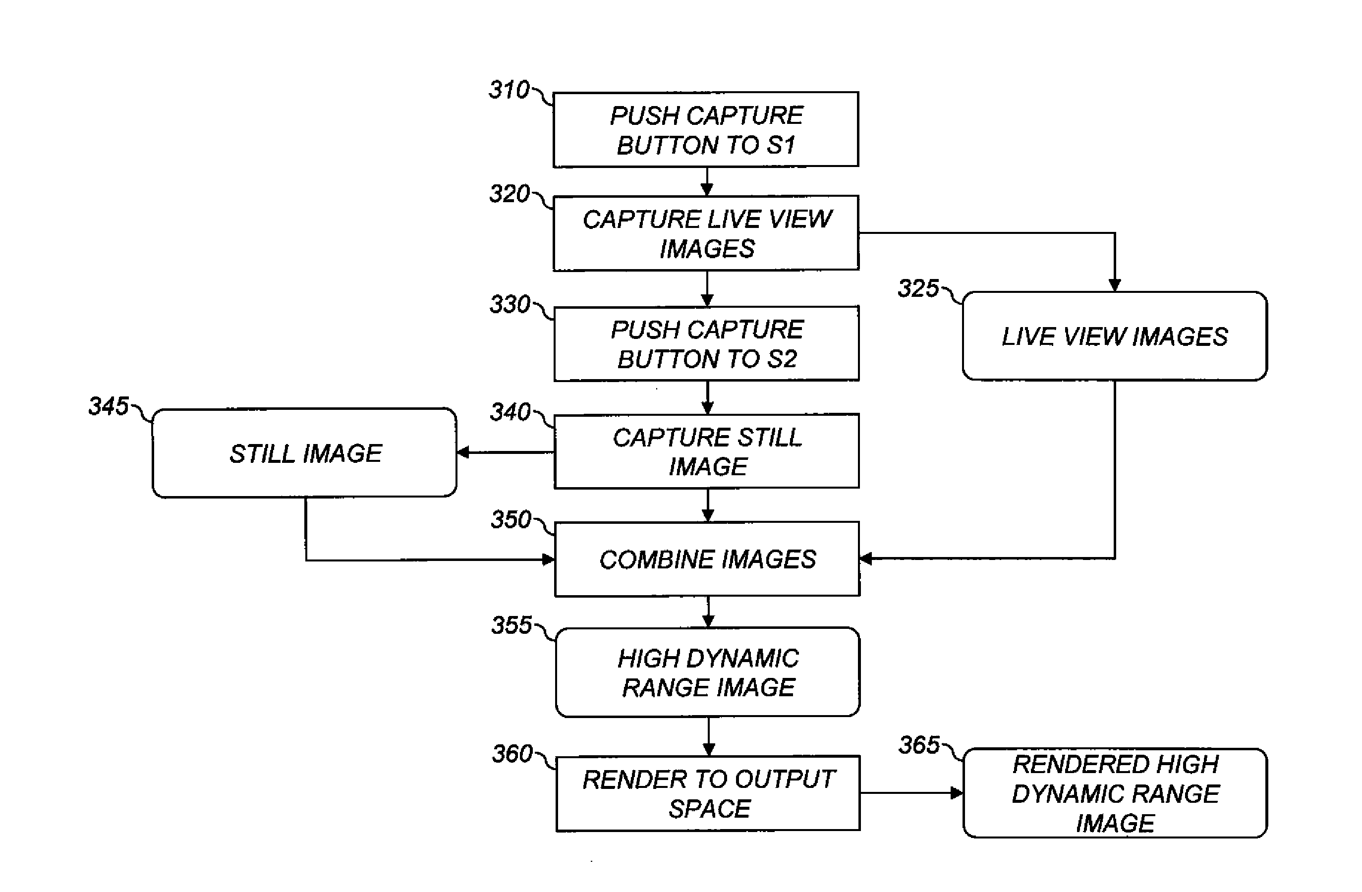
[0040]Turning now to FIG. 1, a block diagram of an image capture device shown as a digital camera embodying the present invention is shown. Although a digital camera will now be explained, the present invention is clearly ...


PUM


Abstract

A method for producing a high-dynamic-range image, comprising: receiving a low-resolution image of a scene having a first resolution and captured at a first exposure level; receiving a first high-resolution image of the scene having a second resolution and captured at a second exposure level different from the first exposure level, the second resolution being greater than the first resolution; forming a residual image corresponding to high spatial frequency content in the first high-resolution image; forming a second high-resolution image having the second resolution and the first exposure level by combining the low-resolution image and the residual image; producing the high-dynamic-range image by combining the first high-resolution image and the second high-resolution image; and storing the high-dynamic-range image in a processor accessible memory.

Description

CROSS REFERENCE RELATED APPLICATION[0001]Reference is made to commonly assigned, U.S. patent application Ser. No. 12 / 644,039 (Docket 95945), filed Dec. 22, 2009, by Wayne E. Prentice, et al., entitled “Creating an Image Using Still and Preview”, and to commonly assigned, U.S. patent application Ser. No. ______ (Docket 96703), filed ______, by Efrain Morales., entitled “Digital camera providing high dynamic range images,” both of which are incorporated herein by reference.FIELD OF THE INVENTION[0002]The invention pertains to generating an improved image by combining multiple images, and more specifically to a method for producing a high resolution image having increased dynamic range.BACKGROUND OF THE INVENTION[0003]Image sensing devices, such as charge-coupled devices (CCDs), are commonly found in such products as digital cameras, scanners, and video cameras. These image sensing devices have a very limited dynamic range when compared to traditional negative film products. A typical ...

Claims


Application Information

Patent Timeline
IPC IPC(8): H04N5/262H04N5/225G06K9/00G06K9/36
CPCG06T5/50H04N5/235H04N5/2355G06T2207/20212G06T5/007G06T2207/10144G06T2207/20016H04N19/30H04N19/59H04N23/70H04N23/741G06T2207/20221G06T5/90
Inventor MORALES, EFRAIN O.
Owner KODAK ALARIS INC
Learn More