
Compact fluorescent lamp with improved performance and size

a fluorescent lamp and compact technology, applied in the field of compact fluorescent lamps, can solve the problems of high cost and long length dimension of fluorescent lamps, and achieve the effects of reducing arc current, increasing protection, and increasing lumen per wattag

Inactive Publication Date: 2012-05-03
GENERAL ELECTRIC CO
View PDF4 Cites 0 Cited by
  • Summary
  • Abstract
  • Description
  • Claims
  • Application Information

AI Technical Summary

Benefits of technology

"The present patent describes a low pressure mercury vapor discharge lamp that includes a spirally wound discharge tube with closely spaced gaps between adjacent turns. The lamp has a compact design and a high lumen per wattage, resulting in a decrease in the need for an extra ballast housing and increased protection against inadvertent contact with the ballast. The lamp also has a longer discharge arc length and a lower arc current, reducing the lamp's maximum overall length and cost. Additionally, the lamp is environmentally friendly as it uses less plastic raw material."

Problems solved by technology

Disadvantages of compact fluorescent lamps, however, are their relatively high cost and longer length dimension.
A current configuration for increasing lamp efficacy for compact fluorescent lamps includes increasing arc length and arc voltage which in turn uses lower arc current resulting in higher lumen output based on the same power consumption.
Another configuration uses a smaller sized electronic ballast and thereby reduces the maximum overall length (MOL) but this lamp configuration increases costs.
The increase in electronic ballast temperature generally reduces system reliability.
However, this prepared solution results in higher costs.

Method used


Image

  • Compact fluorescent lamp with improved performance and size
  • Compact fluorescent lamp with improved performance and size
  • Compact fluorescent lamp with improved performance and size

Examples


example 1

[0029]

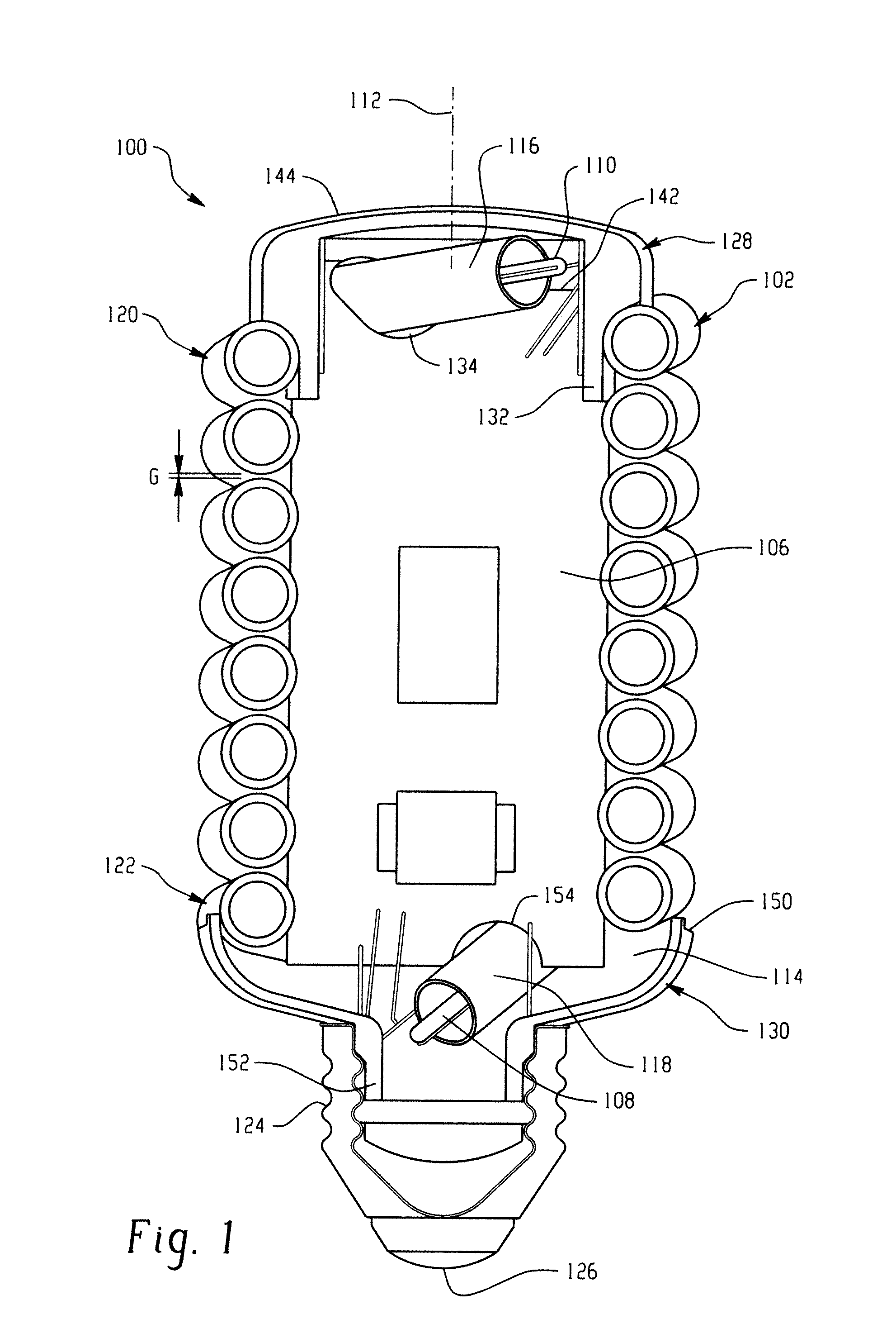
Existing 12 W LampNew 12 W LampMaximum Length112 mm 112 mmSpiral Height (8 turns) 64 mm  64 mmArc Length400 mm1107 mmArc Diameter 45 mm  50 mmTube Diameter  8 mm   8 mm

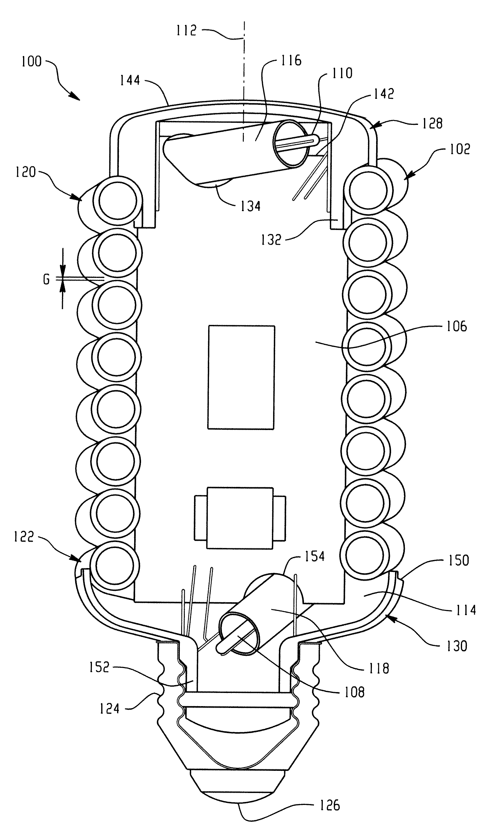
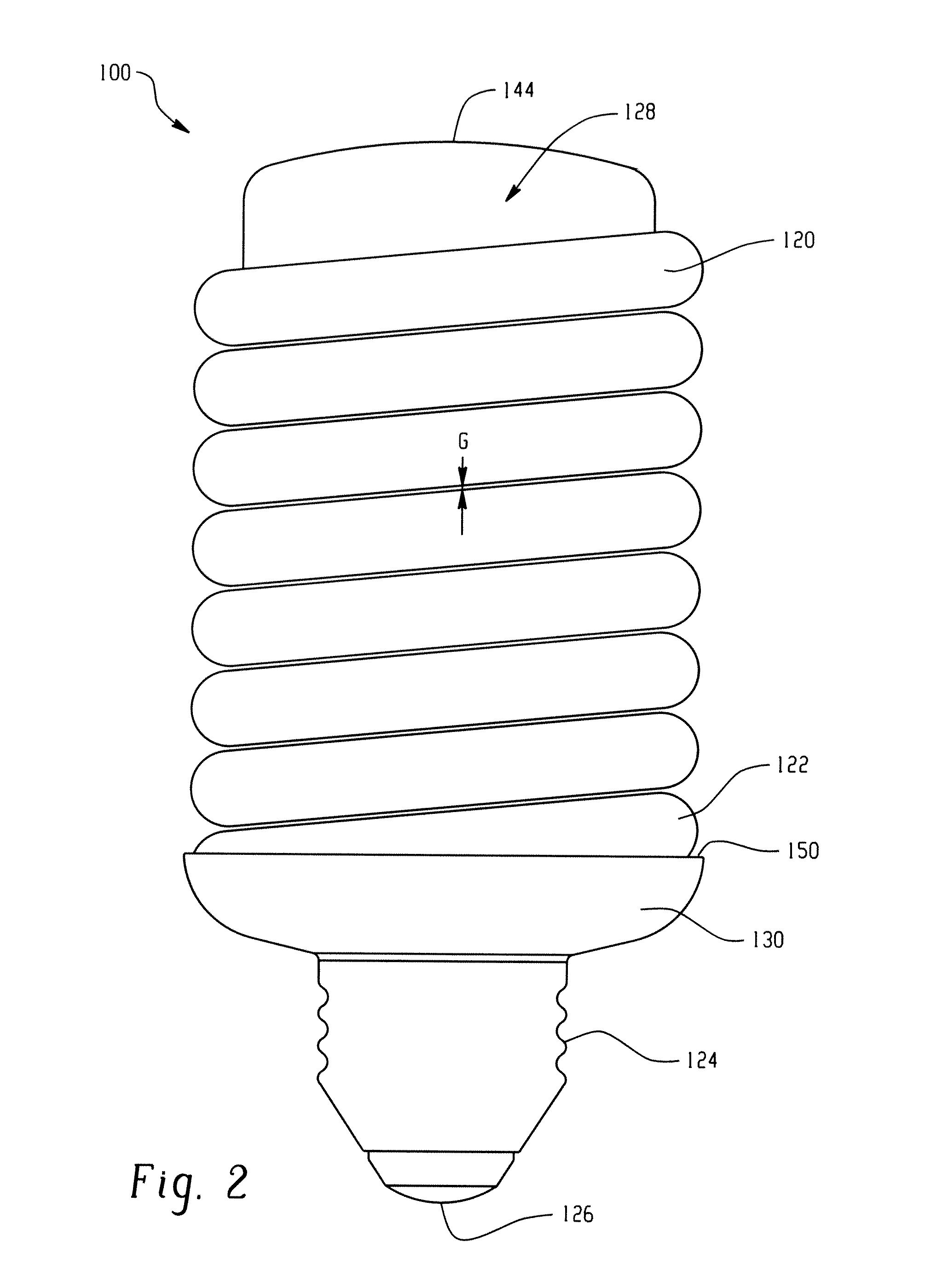
[0030]In summary, the present disclosure achieves an increase in lumens per watt or lamp efficacy and lumen package in a same or reduced lamp size. A self-ballasted compact fluorescent lamp (CFL) is provided by the present disclosure that includes a ballast housing to incorporate the lamp control gear and secures the discharge tube and the base. The housing protrudes from the field surrounded by the glass body which together determines the lamp maximum overall length (MOL). In order to achieve these advantageous features, the discharge tube arrangement is spirally wound wherein the gap between the adjacent turns is reduced close to zero while the sealed ends of the discharge tube are preferably disposed at opposite ends. The gap between adjacent turns of the spirally wound discharge tube is sufficiently small to...


PUM


Abstract

A compact fluorescent lamp includes a discharge tube forming a continuous arc path with electrodes disposed at each end of the path. The lamp includes a fill gas disposed within the discharge tube. The lamp further includes a ballast circuit for controlling current in the discharge tube and operatively connected to the electrodes. The discharge tube is spirally wound around the longitudinal axis of the lamp to form a partially closed cavity and in a preferred arrangement the ballast is positioned within cavity formed by the spirally wound discharge tube. A gap between adjacent turns of the spirally wound discharge tube is less than about 0.5 mm, and preferably about 0.0009 mm.

Description

BACKGROUND OF THE DISCLOSURE[0001]The present disclosure relates to a low pressure mercury vapor discharge lamp and, more specifically, to a compact fluorescent lamp that can replace incandescent lamps of general purpose. The compact fluorescent lamp finds particular application in a wide field of industry and home applications, although it will be appreciated that selected aspects may find application in related environments encountering the same issues with regard to increased lamp efficacy in similar or decreased lamp size.[0002]The majority of known and commercially available low-pressure fluorescent discharge lamps are compact fluorescent lamps. These lamps are intended to replace incandescent lamps used in a wide field of industry and home applications. Main advantages of these lamps are low-power consumption and a long life. Disadvantages of compact fluorescent lamps, however, are their relatively high cost and longer length dimension. Many configurations have been proposed t...

Claims


Application Information

Patent Timeline
Patent Type & Authority Applications(United States)
IPC IPC(8): H01J7/44H01J9/24
CPCH01J61/327H01J61/56Y02B20/19Y02B20/00
Inventor WURSCHING, ISTVANFULOP, JOZSEFPAPP, FERENCBANKUTI, LASZLO
Owner GENERAL ELECTRIC CO
Learn More