
Actuator device for the seat adjustment in a motor vehicle

Active Publication Date: 2012-05-03
FAURECIA AUTOSITZE
View PDF8 Cites 4 Cited by
  • Summary
  • Abstract
  • Description
  • Claims
  • Application Information

AI Technical Summary

Benefits of technology

[0005]It is the underlying objective of the invention to present an actuator device for a seat adjustment in a motor vehicle that allows, first, high production tolerances and, second, enables a simple and thus cost-effective assembly.
[0006]This objective is achieved through an actuator device for a seat adjustment in a motor vehicle as well as through a centering element. The invention features an actuator device for the seat adjustment in a motor vehicle, exhibiting at least one ratchet fitting, a transmission element and an actuator element, whereby the transmission element is centered in the ratchet fitting with a centering element such that the centering element allows for a limited torsional backlash between the transmission element and the ratchet fitting and creates a restoring force against the rotation, whereby said transmission element is connected in a torsionally stiff manner to the actuator element, whereby the actuator element is connected in a form-fitting manner to the centering element.
[0007]According to the invention, at least one ratchet fitting is provided that is actuated by a transmission element. The transmission element is a shaft or rod or a similar torsionally stiff component that is connected in a torsionally stiff manner to the actuator element, which may be a release lever, for example. Essential for the invention is that the connection of the transmission element to the ratchet fitting is made through an inventive centering element. The centering element centers the transmission element in the ratchet fitting and due to its design allows for a limited torsional backlash between the transmission element and the ratchet fitting. However, by its design it generates a restoring force against the rotation as long as the rotation is within the range of the allowed torsional backlash. The actuator element that is torsionally stiff connected to the transmission element is at the same time connected to the centering element in a form-fitting manner.
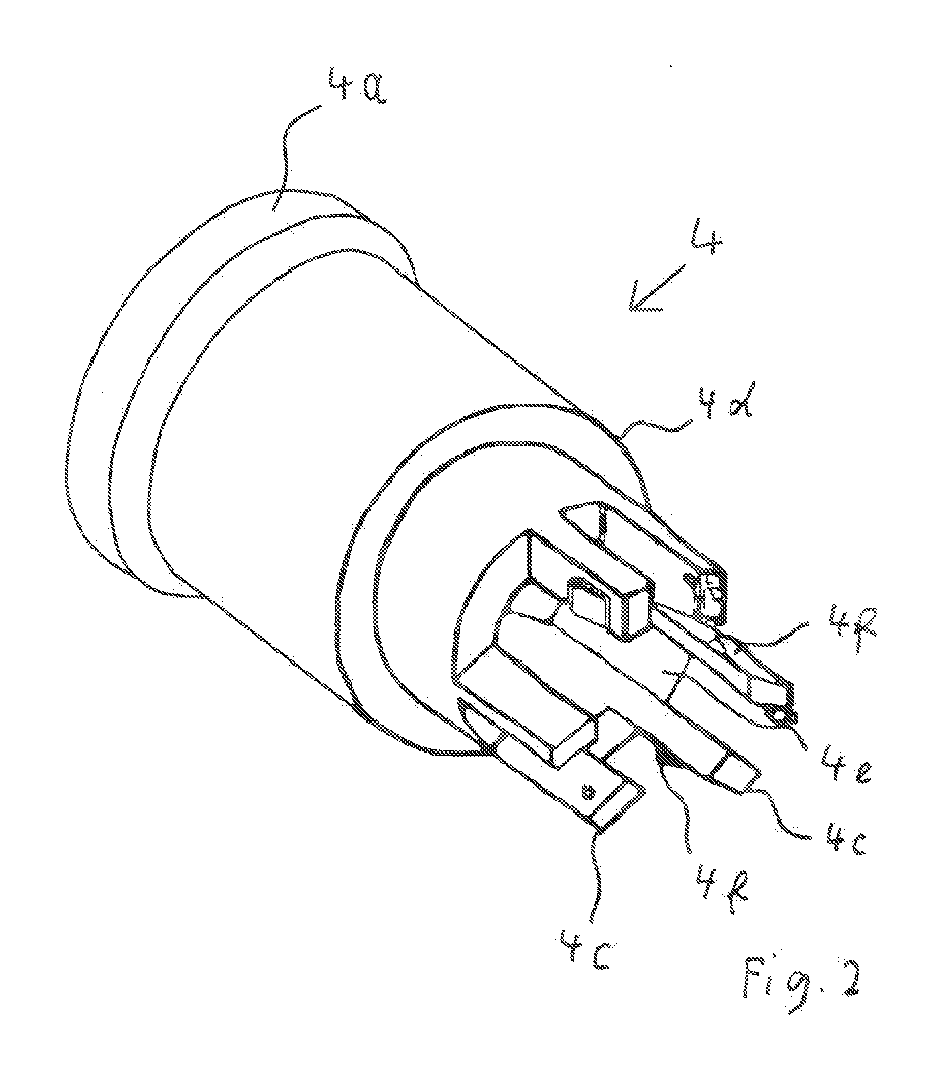
[0010]With such a connection the installation of the seat is made much easier, as the transmission element that is connected, for example, with a second ratchet fitting or a further transmission element leading to the same, which, for example, can be done by a welding process, can be guided loosely through the first ratchet fitting, and can be centered and easily secured in the latter simply by sliding on the centering element, after which an assembly of the actuator element is also possible in a simple manner by a further push-on procedure. Advantageously, here the centering element is designed such that it exhibits an essentially hollow cylinder-like base section. In the area of its internal surface, the base section shaped like a hollow cylinder exhibits a contour that is suited for the form-fitting engagement at a counter-contour to be provided at the transmission element. The contours are designed such that they allow for one, due to their dimensions in relation to the counter contour, a limited torsional backlash, and second present a form-fit that is axially moveable to allow the transmission element to be pushed on and to compensate for the axial tolerances. Preferably, contouring involves at least one groove extending essentially in an axial direction and allowing the torsional backlash based on its width selected in the circumferential direction.

Problems solved by technology

The required mechanical coupling of the two ratchet fittings with the actuator element necessary for this brings with it the problem of the relative position tolerances of the two ratchet fittings towards each other.
However, if for example two fittings are to be coupled, as is shown in EP 0 098 400 B1, then both fittings must be coupled using a transmission element, which, for one, requires increased demands on the position tolerances of the fittings in relation to each other, and secondly entails a more complex assembly of the actuator device.

Method used


Image

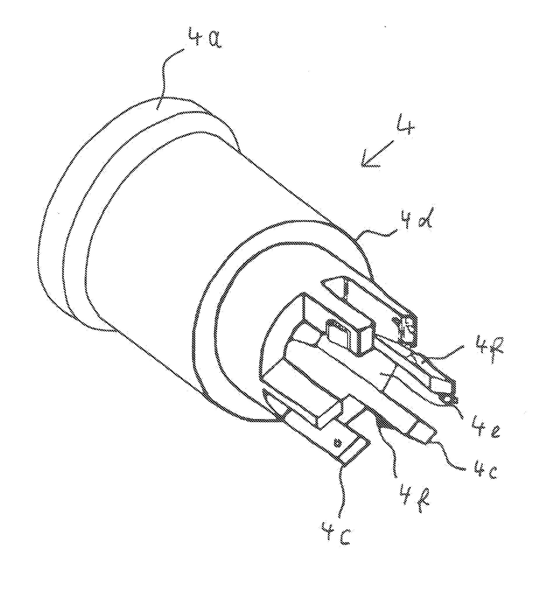
  • Actuator device for the seat adjustment in a motor vehicle
  • Actuator device for the seat adjustment in a motor vehicle
  • Actuator device for the seat adjustment in a motor vehicle

Examples


Embodiment Construction

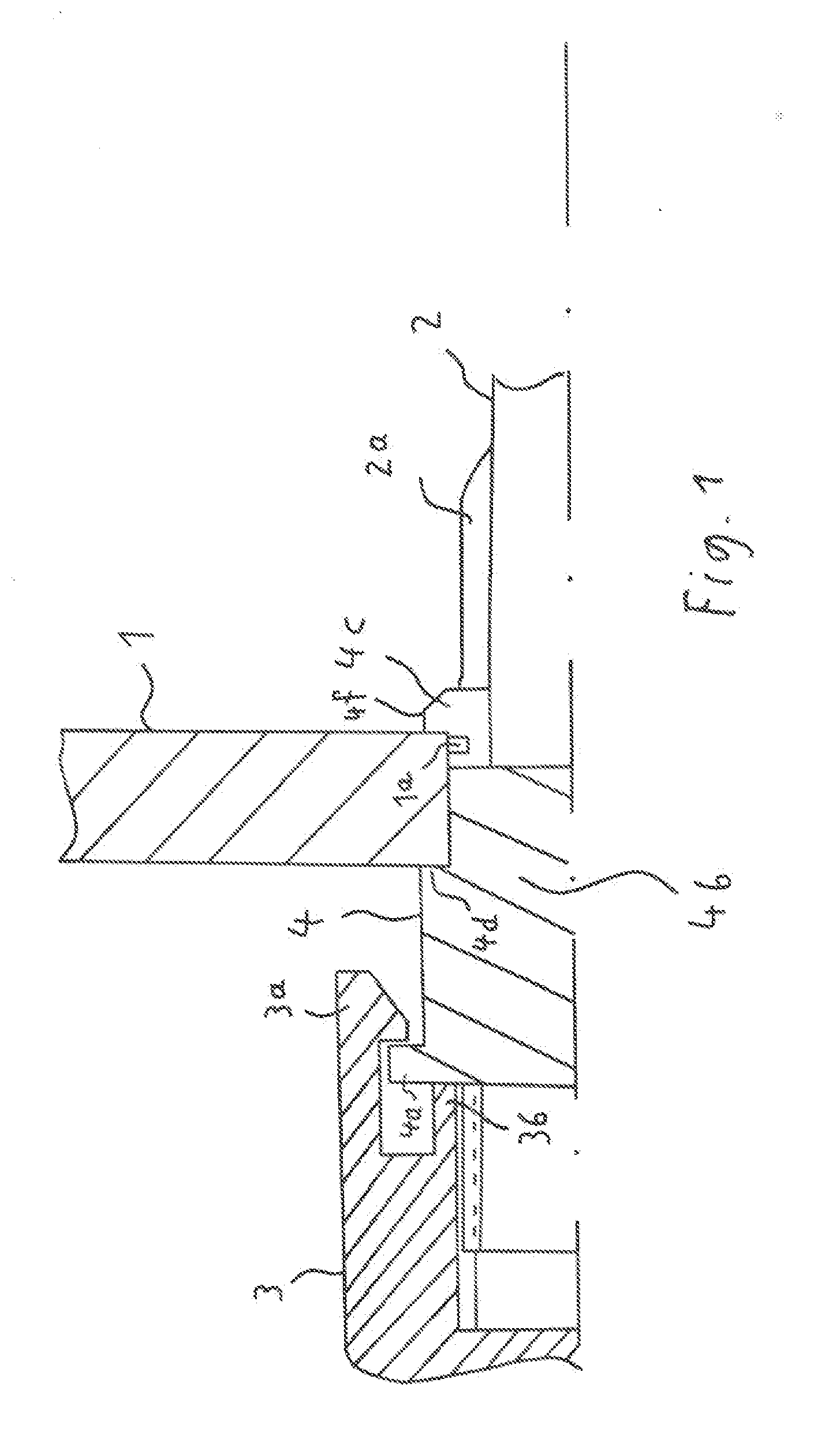
[0021]Typically, a ratchet fitting 1, FIG. 1, is designed such that it exhibits a central borehole for receiving an actuator mechanism that is suited for receiving a transmission element 2 with the release of the ratchet fitting 1 occurring through a rotation of the transmission element 2. Typically a driver 1a is provided at the ratchet fitting 1, for example designed in the shape of a cam that interacts with a suitable contour of the transmission element 2. According to the invention, the transmission element 2, which may be a rod, a tube, a shaft or a similar torsionally stiff structure, is in its radial dimensions significantly smaller dimensioned than would be appropriate for conventional direct mounting in the borehole of the ratchet fitting 1 with regard to a secure support. Instead, a centering element 4 is pushed onto the transmission element 2 and inserted into the borehole in the ratchet fitting 1 until it reaches an end position defined by a stop. The stop may be, for ex...


PUM


Abstract

An actuator device for the seat adjustment in a motor vehicle, exhibiting at least one ratchet fitting (1), a transmission element (2) and an actuator element (3), whereby the transmission element (2) is centered in the ratchet fitting (1) with a centering element (4) such that the centering element (4) allows for a limited torsional backlash between the transmission element (2) and the ratchet fitting (1) and creates a restoring force against the rotation, whereby said transmission element (2) is connected in a torsionally stiff manner to the actuator element (3), whereby the actuator element (3) is connected in a form-fitting manner to the centering element (4).

Description

CROSS-REFERENCE TO RELATED APPLICATIONS[0001]This application claims priority from German Patent Application 10 2010 019 029.2-14 titled “Actuator Device for the Seat Adjustment in a Motor Vehicle”, which was filed on May 3, 2010 and incorporated fully herein by reference.TECHNICAL FIELD[0002]The invention relates to an actuator device for the seat adjustment in a motor vehicle as well as to a centering element.BACKGROUND INFORMATION[0003]With motor vehicle seat adjustments, it is currently common to use ratchet fittings that can be unlocked by the user via an actuator element, for example a lever, and in the unlocked condition allow for pivoting an element of the vehicle seat, in particular the backrest of the vehicle seat. Often, these ratchet fittings are provided on both sides of the vehicle seat. In such cases, the unlocking mechanism must be designed in such a way as to allow for the simultaneous unlocking of both ratchet fittings.[0004]The required mechanical coupling of the ...

Claims


Application Information

Patent Timeline
IPC IPC(8): B60N2/02F16F1/14B60N2/90
CPCB60N2/20B60N2205/50B60N2/22
Inventor NAUGHTON, MICHAEL
Owner FAURECIA AUTOSITZE
Learn More