
Carbon nanotube film supporting structure and method for using same

a carbon nanotube and film technology, applied in the direction of ceramicware, caps, liquid handling, etc., can solve the problems of carbon nanotube adhesive, difficult to handle, easy damage or destruction of film,

Active Publication Date: 2012-05-03
BEIJING FUNATE INNOVATION TECH
View PDF18 Cites 12 Cited by
  • Summary
  • Abstract
  • Description
  • Claims
  • Application Information

AI Technical Summary

Benefits of technology

The present patent is about a carbon nanotube film supporting structure and a method for using it. The structure is designed to protect and support a carbon nanotube film structure, which can be peeled off completely from the supporting structure. The supporting structure includes a body with a surface, and a support region on the surface. The support region has a ratio of micropores to the support region area greater than or equal to 80%, meaning that the effective contact area between the carbon nanotube film structure and the support region is less than or equal to 20%. The carbon nanotube film structure can be peeled off completely after being in contact with the supporting structure. The body can be made of metal, metal oxide, ceramics, or resin, and the shape and size of the body are not limited. The surface of the body can be a flat surface, a curved surface, or an irregular surface. The micropores are distributed throughout the support region area. The technical effect of this patent is to provide a better way to support and protect carbon nanotube film structures, allowing for easier handling and use in various applications.

Problems solved by technology

However, because carbon nanotubes are microscopic structures, it is necessary to assemble the carbon nanotubes at a macroscopic level.
However, this kind of carbon nanotube film is very thin.
An external mechanical force applied on the carbon nanotube film may easily damage or destroy the film.
Furthermore, the carbon nanotube film has an extremely large specific surface area, which makes the carbon nanotubes adhesive and difficult to handle, particularly if a large amount of carbon nanotube films are fabricated.

Method used


Image

  • Carbon nanotube film supporting structure and method for using same
  • Carbon nanotube film supporting structure and method for using same
  • Carbon nanotube film supporting structure and method for using same

Examples


Embodiment Construction

[0018]The disclosure is illustrated by way of example and not by way of limitation in the figures of the accompanying drawings in which like references indicate similar elements. It should be noted that references to “an” or “one” embodiment in this disclosure are not necessarily to the same embodiment, and such references mean at least one.

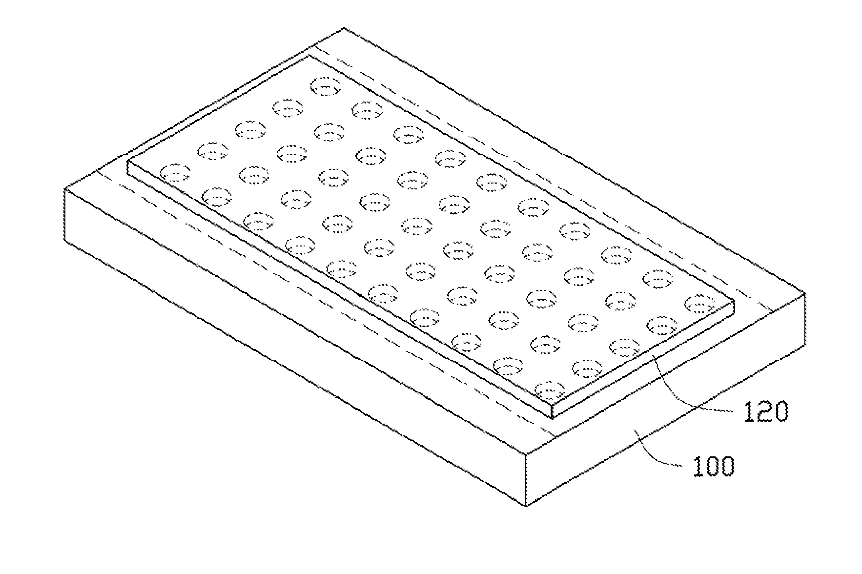
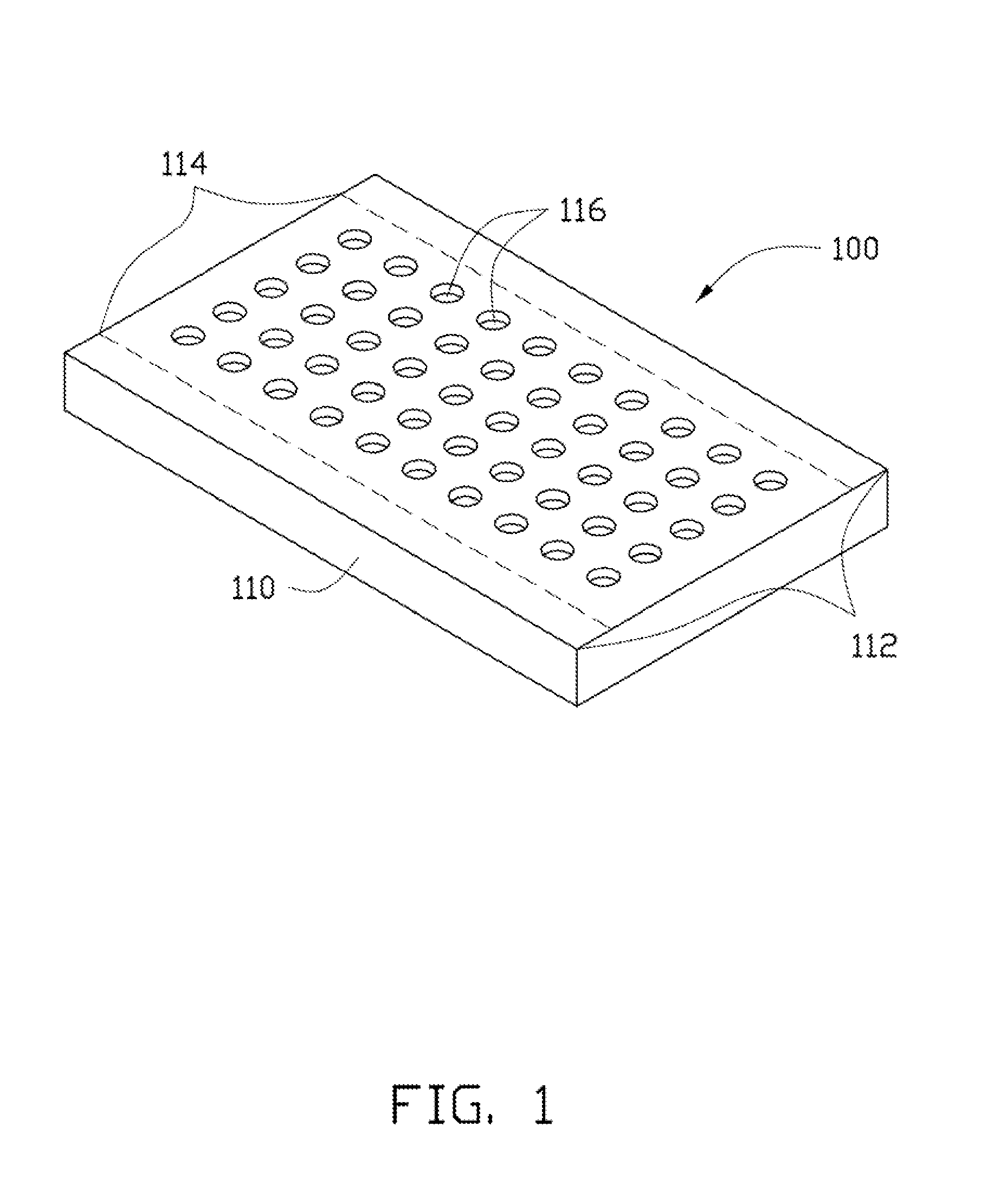
[0019]Referring to FIG. 1, a carbon nanotube film supporting structure 100 is provided. The carbon nanotube film supporting structure 100 can be used for supporting or protecting a carbon nanotube film structure. The carbon nanotube film structure can be peeled off completely from the carbon nanotube film supporting structure 100. The carbon nanotube film supporting structure 100 includes a body 110 having a surface 112. A support region 114 is one part of the surface 112. A number of micropores 116 are, uniformly or not, defined in the support region 114.

[0020]A ratio of a plurality of micropores area to a support region area, as defined by a co...


PUM

PropertyMeasurementUnit
distanceaaaaaaaaaa
diameteraaaaaaaaaa
diameteraaaaaaaaaa

Abstract

A carbon nanotube film supporting structure is provided. The carbon nanotube film supporting structure is used for supporting a carbon nanotube film structure. The carbon nanotube film supporting structure includes a body and a number of voids. The body has a surface defining a support region. The voids are defined in the support region. A void ratio of the support region is greater than or equal to 80%. The present disclosure also provides a method for using the carbon nanotube film supporting structure.

Description

CROSS-REFERENCE TO RELATED APPLICATIONS[0001]This application claims all benefits accruing under 35 U.S.C. §119 from China Patent Application No. 201010521687.5, filed on Oct. 27, 2010 in the China Intellectual Property Office, the disclosure of which is incorporated herein by reference. This application is related to applications entitled, “CARBON NANOTUBES FILM SUPPORTING STRUCTURE AND METHOD FOR USING THE SAME”, filed ______ (Atty. Docket No. US34822).BACKGROUND[0002]1. Technical Field[0003]The present disclosure relates to a carbon nanotube film supporting structure and a method for using the carbon nanotube film supporting structure.[0004]2. Description of Related Art[0005]Carbon nanotubes are tubules of carbon generally having diameters ranging from 0.5 nanometers to 100 nanometers. Carbon nanotubes have recently attracted a great deal of attention for use in different applications such as field emitters, gas storage and separation, chemical sensors, and high strength composit...

Claims


Application Information

Patent Timeline
Patent Type & Authority Applications(United States)
IPC IPC(8): F16M13/00B65B7/00B82Y30/00
CPCC04B38/0074C04B2111/00612C04B35/10C04B38/0054
Inventor FENG, CHENWANG, YU-QUANLIU, LIANGQIAN, LI
Owner BEIJING FUNATE INNOVATION TECH
Learn More