
Energy-Optimal Control Decisions for Systems

Active Publication Date: 2012-04-26
VIGILENT CORP
View PDF5 Cites 87 Cited by
  • Summary
  • Abstract
  • Description
  • Claims
  • Application Information

AI Technical Summary

Benefits of technology

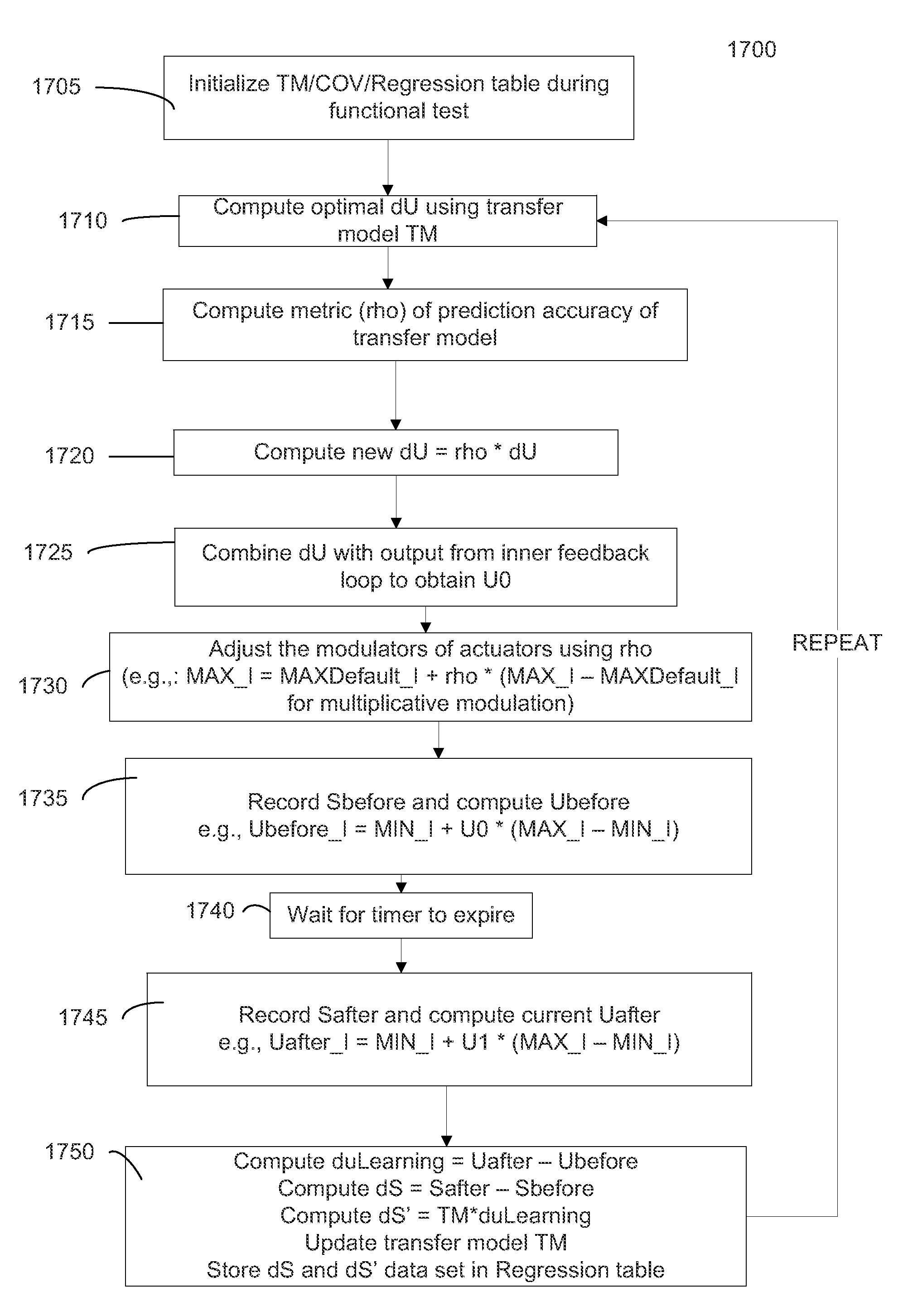
[0015]Sometimes control actions are computed that reduce the penalty function, but don't necessarily minimize it. The decision to use a sub-optimal predictive control decision may be randomized, and / or may have a randomized level of sub-optimality. These sub-optimal predictive control actions are taken to ensure that the learning process has “persistently exciting” data, which can improve the accuracy of the transfer model predictions.

Problems solved by technology

However, such precautionary measures waste energy.
While it is possible to manually turn off redundant HVAC units to save energy, doing so poses a risk of overheating that equipment.
Furthermore, the complex and tightly coupled airflow patterns in a data center make it difficult for an operator to know which HVAC unit will be the most effective to restart should a need be identified.
Current methods can also be unstable if more complex algorithms are attempted.

Method used


Image

  • Energy-Optimal Control Decisions for Systems
  • Energy-Optimal Control Decisions for Systems
  • Energy-Optimal Control Decisions for Systems

Examples


Embodiment Construction

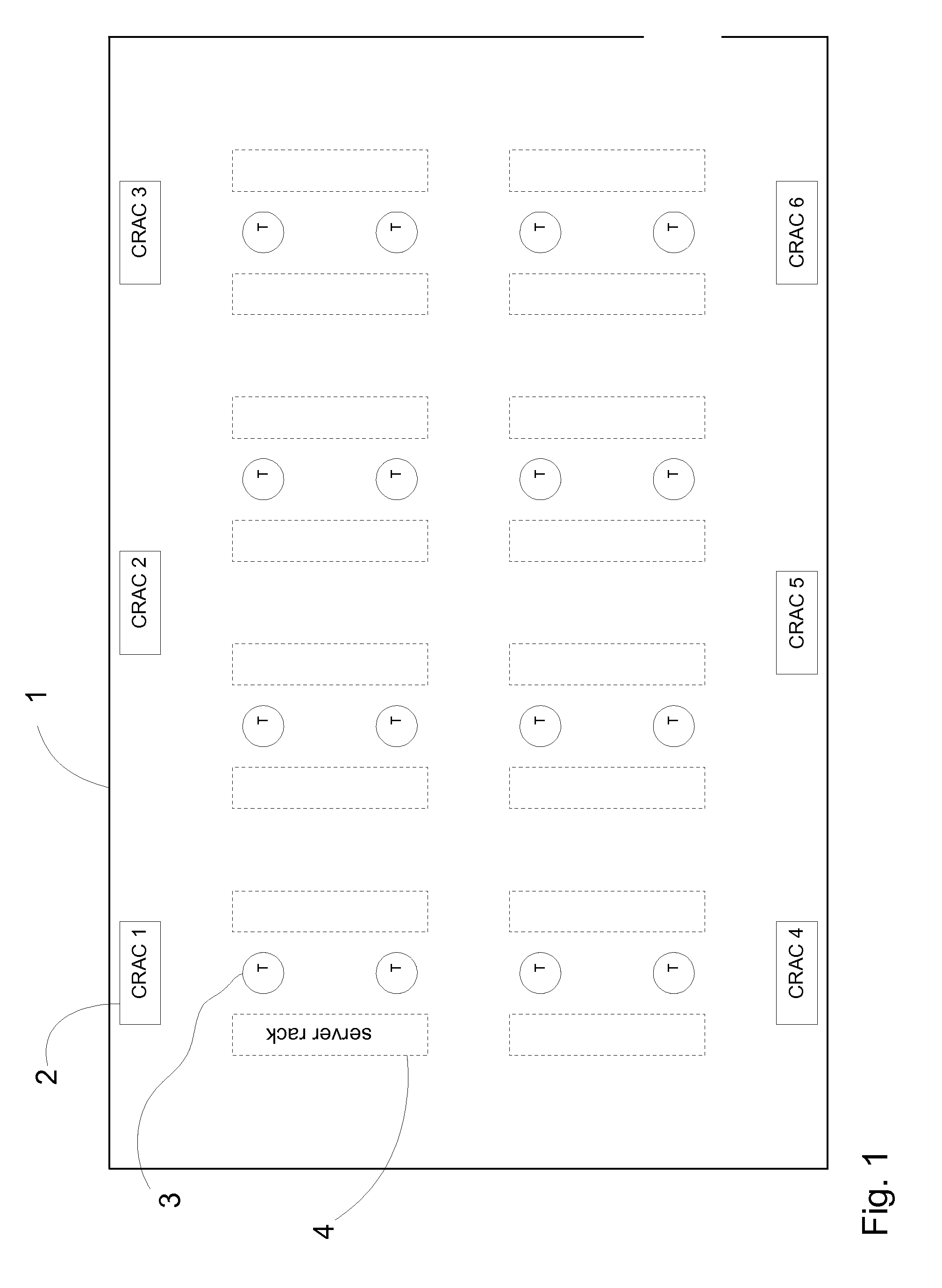
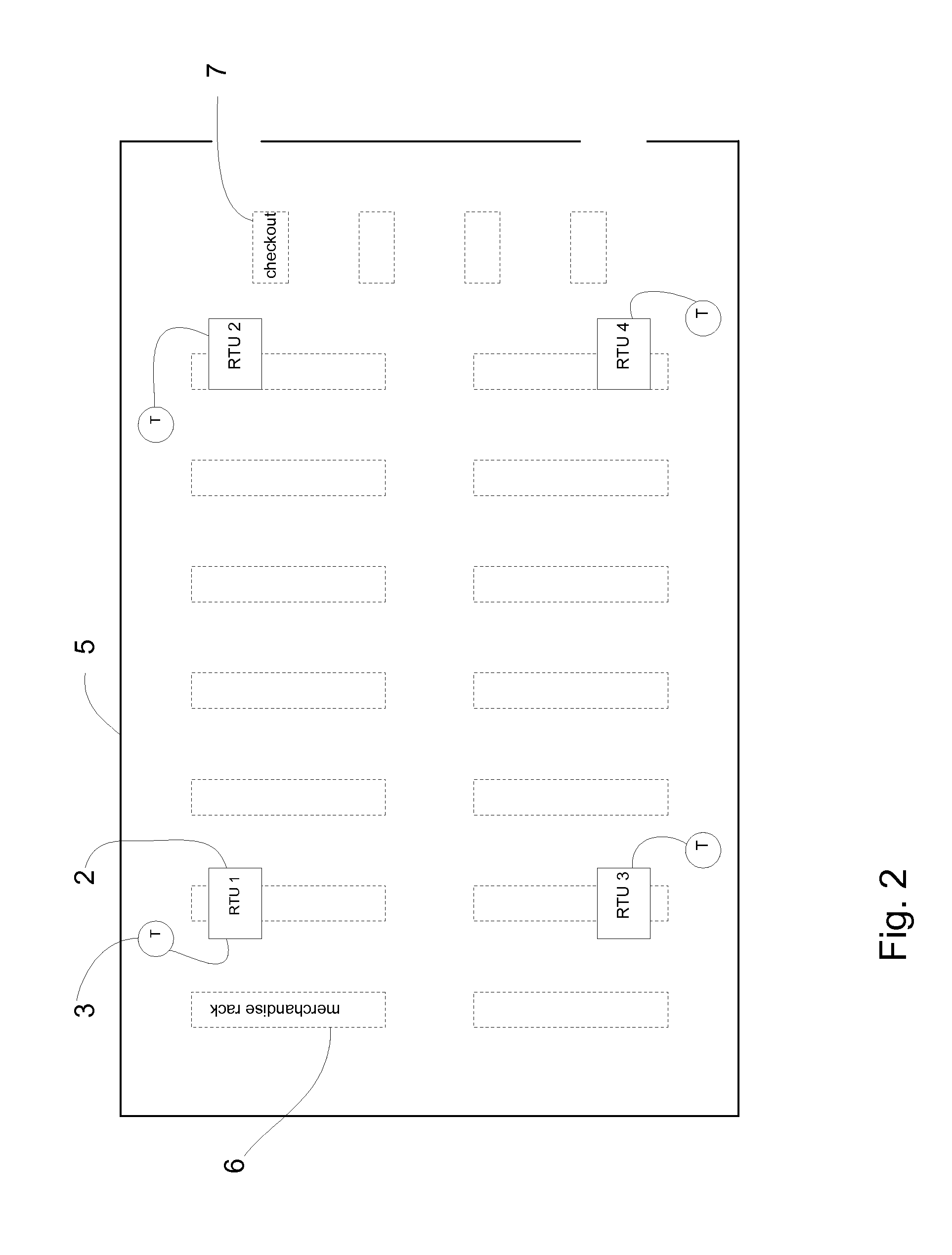
[0040]To ensure that an environment (e.g. a data center) is sufficiently cool or warm, standard operating procedure is to operate extra HVAC units (or other environmental maintenance modules) beyond what is marginally required. However, such precautionary measures waste energy. Various embodiments can analyze sensors throughout the environment (e.g., sensors across modules or at locations outside of modules) to determine whether the operation levels of specific modules can be safely reduced and whether increased operation is required (e.g. due to an out-of-range measurement), including which module is optimal for bringing the sensor back in range. Such embodiments can provide stable environments while reducing energy consumption. A transfer model (e.g., a matrix or set of matrices) can be used in performing the above determinations. In one aspect, the transfer model can provide a relation between a change in operation level of a module and resulting temperature differences for each ...


PUM


Abstract

Methods, systems, and apparatuses are provided for controlling an environmental maintenance system that includes a plurality of sensors and a plurality of actuators. The operation levels of the actuators can be determined by optimizing a penalty function. As part of the penalty function, the sensor values can be compared to reference values. The optimized values of the operation levels can account for energy use of actuators at various operation levels and predicted differences of the sensor values relative to the reference values at various operation levels. The predicted difference can be determined using a transfer model. An accuracy of the transfer model can be determined by comparing predicted values to measured values. This accuracy can be used in determining new operational levels from an output of the transfer model (e.g., attenuating the output of the transfer model based on the accuracy).

Description

CROSS-REFERENCES TO RELATED APPLICATIONS[0001]The present application claims the benefit of U.S. Provisional Application No. 61 / 375,778, entitled “ENERGY-OPTIMAL CONTROL DECISIONS FOR HVAC SYSTEMS”, filed Aug. 20, 2010, the entire contents of which are herein incorporated by reference for all purposes.[0002]The present application is related to commonly owned filed non-provisional application “Method And Apparatus For Efficiently Coordinating Data Center Cooling Units” by Federspiel et al. (Attorney Docket No. 027332-000510US) (hereinafter Federspiel II) and is also related to U.S. Non-Provisional application Ser. No. 12 / 396,944 by C. Federspiel, entitled “Method and Apparatus for Coordinating the Control of HVAC Units” (Attorney Docket No. 027332-000110US) filed Mar. 3, 2009 (hereinafter Federspiel I), the entire contents of which are herein incorporated by reference for all purposes.BACKGROUND[0003]The present invention generally relates to environmental control systems, such as h...

Claims


Application Information

Patent Timeline
IPC IPC(8): G05D11/00F24F11/76
CPCH05K7/20836G05D23/1934H05K7/1498F24F11/006F24F11/30F24F11/62F24F11/77F24F11/58F24F11/46F24F11/63G05D23/00G05B13/026
Inventor FEDERSPIEL, CLIFFORD C.CHIN, JERRY
Owner VIGILENT CORP
Learn More