
Method of controlling a power plant

Inactive Publication Date: 2014-05-22
SIEMENS AG
View PDF3 Cites 11 Cited by
  • Summary
  • Abstract
  • Description
  • Claims
  • Application Information

AI Technical Summary

Benefits of technology

The patent is about a method to optimize the use of renewable power production facilities and storage facilities in a power grid. The method allows for the controlled combination of these facilities to provide a steady power input and important ancillary services such as stabilizing the power system, providing frequency response, and matching seasonal load. The control of the power facilities is implemented based on a combined droop of the facilities, which ensures minimal energy spill and reduced mechanical load on production facilities when responding to frequency events. The technical effects of this method include maximizing the utilization of renewable power production facilities and minimizing energy wastage in the power grid.

Problems solved by technology

This can lead to situations in which it is difficult for a renewable power plant to reach grid compliance without “spilling” energy.
At present, these and similar situations often result in renewable power plants such as wind power plants having to “spill”, i.e. waste, valuable energy.
Another drawback of the established power networks is that only the grid operator can make use of a power storage facility in which a power “surplus” on the grid could be converted into a form suitable for storage and for later retrieval, for example for delivering energy back into the grid.

Method used


Image

  • Method of controlling a power plant
  • Method of controlling a power plant
  • Method of controlling a power plant

Examples


Embodiment Construction

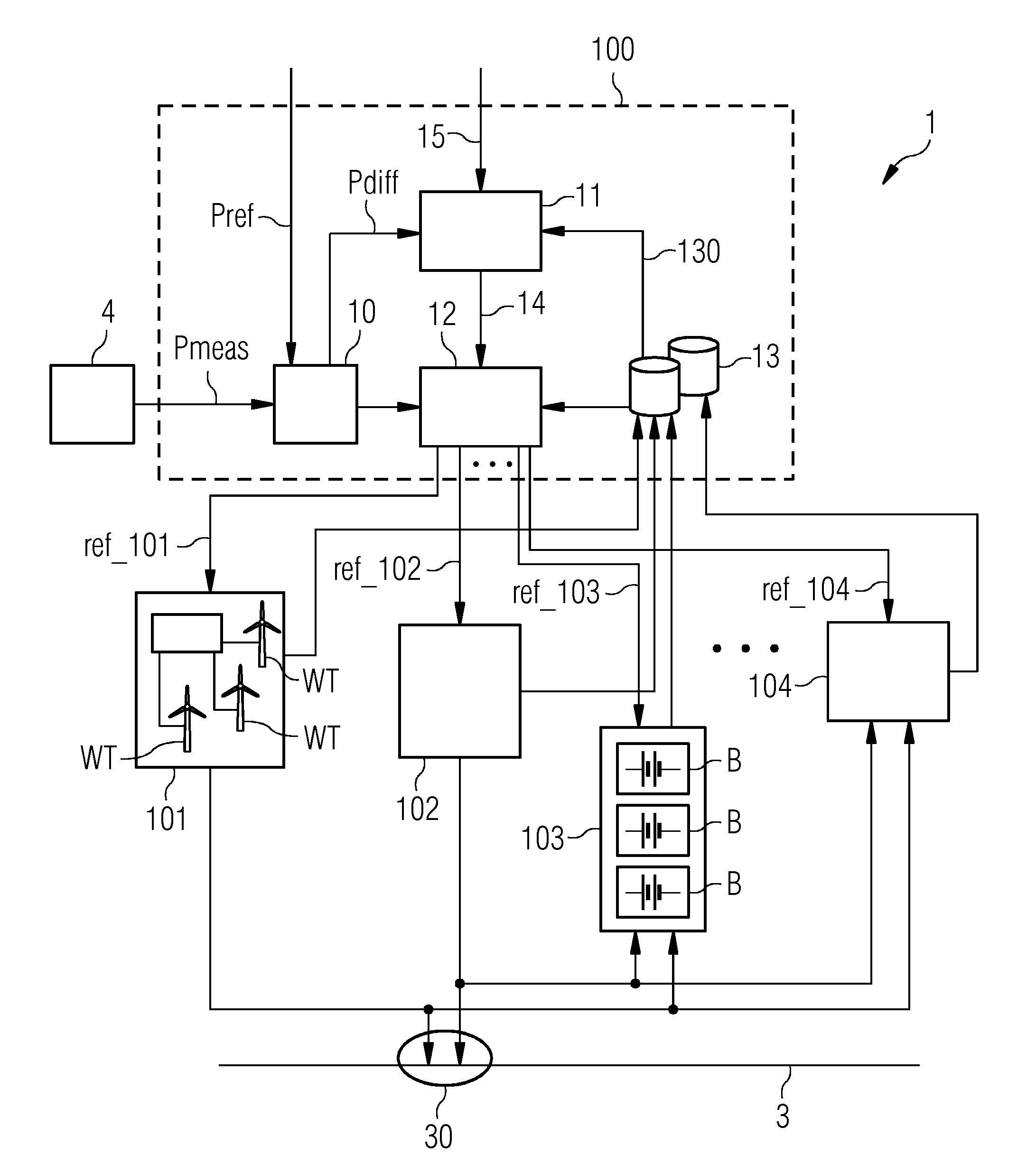
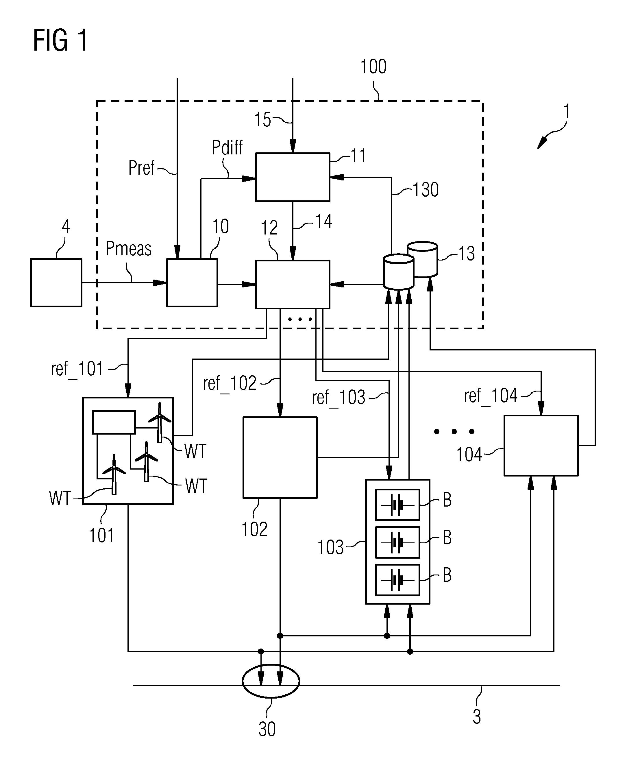
[0047]FIG. 1 shows a functional block diagram of a power plant controller 100 in a power plant 1 according to an embodiment. The power plant controller 100 can control a plurality of power facilities 101, 102, 103, 104. Here, the power facilities comprise a first wind park 101 with a number of wind turbines WT, a second renewable power production facility 102, a power storage facility 103 such as a battery or hydroelectric station, and another power storage facility 104. Of course, the power plant 1 can comprise any number of renewable power production facilities and any number of power storage facilities, any combination of power production and power storage facilities, and is not limited to the types mentioned here. In this embodiment, the power production facilities 101, 102 and power storage facilities 103, 104 are interconnected, i.e. power can be transferred between these facilities independently of the grid 3, indicated by the arrows. Of course, although not shown here, the p...


PUM


Abstract

A method of controlling a power plant connected at a point of connection to an electricity grid is provided. The power plant includes a renewable power production facility connected to a power storage facility. The method includes determining an active power grid demand of the electricity grid, obtaining operating data for the renewable power production facility and the power storage facility, determining, on the basis of the grid demand and the operating data, active power transfer quantities to be transferred between the renewable power production facility and the power storage facility and / or from the power plant facility to the grid, computing active power references for the facility of the power plant on the basis of the active power transfer quantities, and operating the power plant facility on the basis of the active power references. Further, a plant controller for controlling such a power plant and a power plant are provided.

Description

FIELD OF INVENTION[0001]A method of controlling a power plant, a power plant controller and a power plant are provided.BACKGROUND OF INVENTION[0002]A grid operator or balancing authority may determine the base amount of active power that power producing facilities such as fossil plants, hydro plants or wind power plants may be allowed to produce at any specific time, i.e. the amount of power required by customers supplied by the grid, and issue appropriate references to any power plant that feeds into the grid. Such power plants are generally characterized by their ability to regulate the real or active power within some dynamic range depending on various factors such as environmental conditions, the number of power production units up and running, the type of technology used by the power plant, etc. The active power response rate and the reactive power response rate of a power plant also depend on the plant type. The proportions of active power and reactive power that are required ...

Claims


Application Information

Patent Timeline
IPC IPC(8): G06F1/26
CPCH02J7/34H02J3/382H02J3/32G06F1/26Y02E70/30H02J2300/20H02J3/381H02J3/466H02J3/48
Inventor NIELSEN, KAJ SKOVSTOETTRUP, MICHAEL
Owner SIEMENS AG
Learn More