Lighting device and illumination apparatus using same

a technology of illumination apparatus and switching device, which is applied in the direction of lighting apparatus, electroluminescent light sources, light sources, etc., can solve the problems of flickering on the captured images, noise from transformers, and difficulty in precisely controlling the switching device by using pulses, so as to prevent flickering

Inactive Publication Date: 2012-04-26
PANASONIC INTELLECTUAL PROPERTY MANAGEMENT CO LTD
View PDF28 Cites 9 Cited by
  • Summary
  • Abstract
  • Description
  • Claims
  • Application Information

AI Technical Summary

Benefits of technology

[0012]With the above configuration, it is possible to prevent flickering from occur...

Problems solved by technology

Accordingly, it becomes difficult to exactly control a switching device by using a pulse.
Further, a noise occurs due to a transformer or the like.
However, since a vide...

Method used


Image

  • Lighting device and illumination apparatus using same
  • Lighting device and illumination apparatus using same
  • Lighting device and illumination apparatus using same

Examples


first embodiment

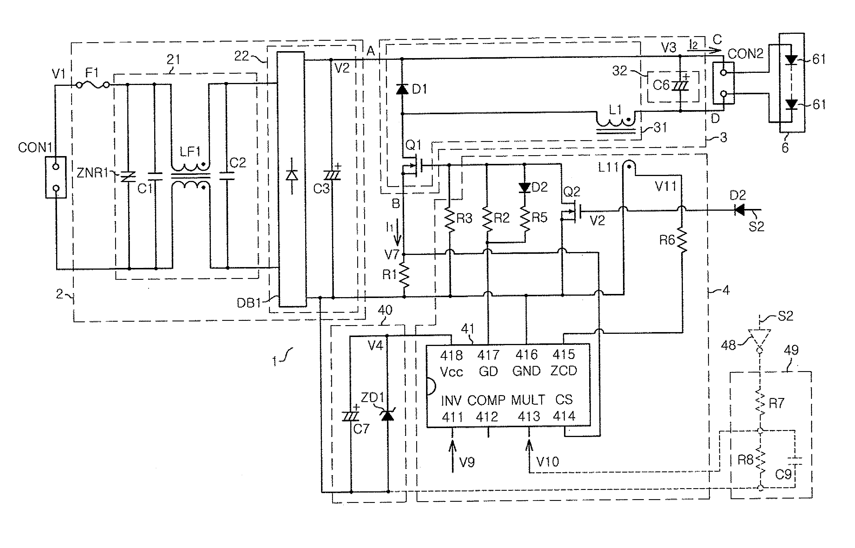
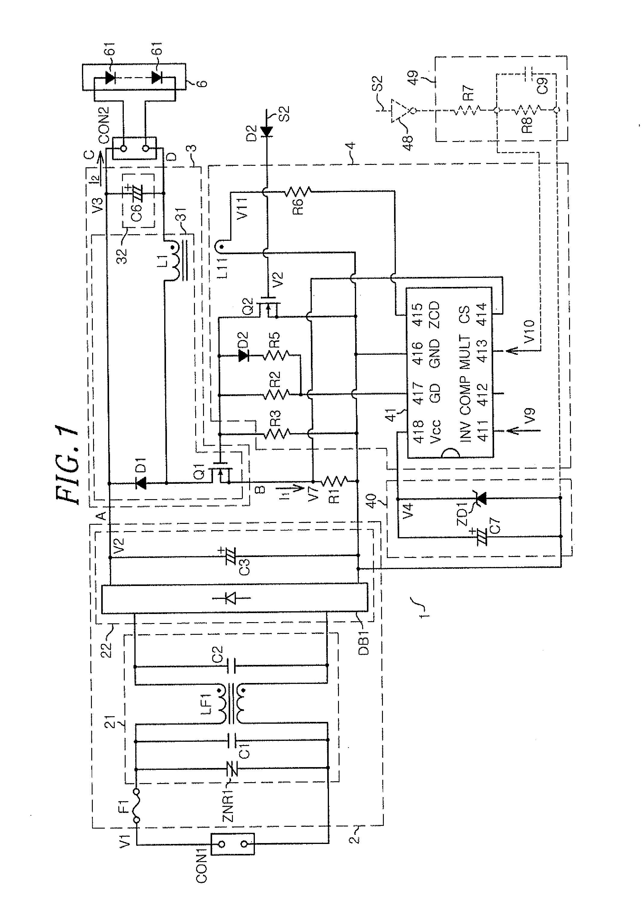
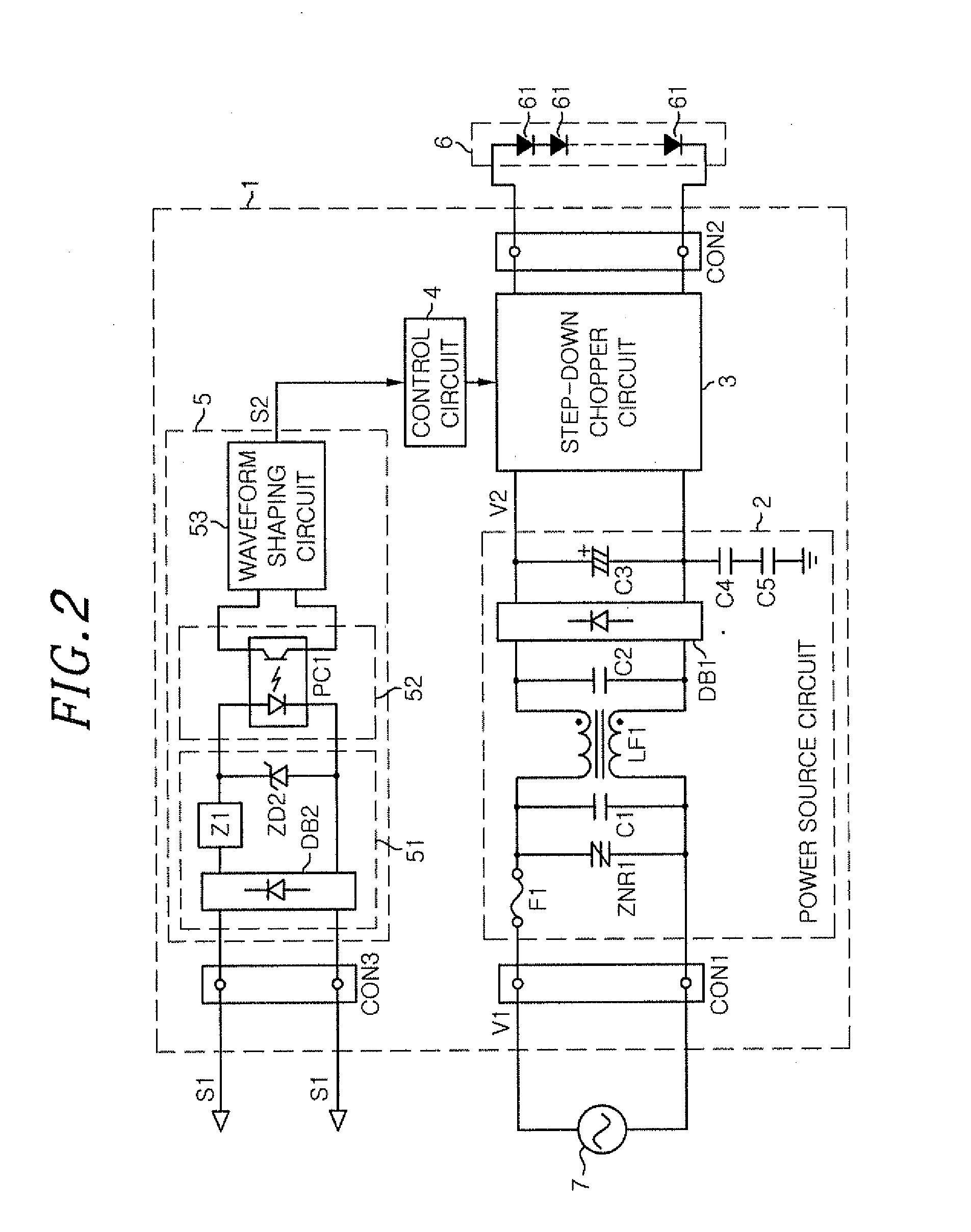
[0022]FIG. 2 illustrates a circuit configuration of a lighting device 1 in accordance with a first embodiment of the present invention.

[0023]The lighting device 1 of this embodiment includes a power circuit 2, a step-down chopper circuit 3, a control circuit 4 and a signal process unit 5.

[0024]The lighting device 1 is supplied with power from a commercial power source 100 (e.g., 100 V, 50 / 60 Hz) via a connector CON1. The power circuit 2 converts an alternating current (AC) voltage V1 into a rectified voltage V2. Further, a dimming signal S1 is inputted to the signal processing unit 5 via a connector CONS, and the signal processing unit 5 performs a process on the dimming signal S1 to produce a PWM signal S2. The PWM signal S2 is outputted to the control circuit 4.

[0025]Further, the step-down chopper circuit 4 is connected to the light source 6 via a connector CON2. In the present embodiment, the light source 6 includes at least one semiconductor light emitting element (LED element) ...

second embodiment

[0088]An illumination apparatus 8 in accordance with a second embodiment of the present invention includes the light source 6 and the lighting device 1 of the first embodiment. FIG. 6 illustrates a schematic cross-sectional view of the illumination apparatus 8.

[0089]In the illumination apparatus 8 of this embodiment, the light source 6 and the lighting device 1 serving as a power source unit are separately provided and electrically connected to each other via lead wires 81. By separately providing the lighting device 1 and the light source 6, the light source 6 can become thinner. Further, a degree of freedom in an installation place of the lighting device 1 is improved.

[0090]The light source 6 is an LED module having the LED elements 61, a housing 62, a light diffusion plate 63 and a mounting substrate 64. The light source 6 is buried in a ceiling 9 from which a surface of the light source 6 is exposed.

[0091]The housing 62 is formed of a cylindrical metal body with one surface open...


PUM


Abstract

A lighting device includes: a lighting unit which outputs a direct current; a smoothing unit having a capacitor which smoothes the direct current outputted from the lighting unit and supplies it; and a control unit for performing an intermittent control which alternately repeats a first time period in which the direct current is supplied to the smoothing unit and a second time period in which the direct current decreases to be smaller than that in the first time period. In the lighting device, a product of a frequency (Hz) and a capacitance (μF) of the capacitor is equal to or greater than 0.05 in which one cycle of the frequency corresponds to a sum of the first time period and the second time period.

Description

FIELD OF THE INVENTION[0001]The present invention relates to a lighting device and an illumination apparatus using the same.BACKGROUND OF THE INVENTION[0002]Conventionally, there is known a lighting device using light emitting diodes (LEDs) as a light source. In order to control the LED brightness, the conventional lighting device performs PWM dimming control in which a current flowing in the LED intermittently stops at a low frequency within a range from about 100 Hz to several kHz, or amplitude dimming control for changing an amplitude of the LED current. In the PWM dimming control, brightness of the LED is controlled by changing a time period (on duty) for supplying the LED with a current, and controlling an average value of an optical power (LED current). In the amplitude dimming control, brightness of the LED is controlled by changing a magnitude (amplitude) of the LED current, and controlling an average value of the optical power (LED current).[0003]When the PWM dimming contro...

Claims


Application Information

Patent Timeline
IPC IPC(8): H05B37/02H05B44/00
CPCH05B33/0815H05B45/39H05B45/375H05B45/3725H05B45/38H05B45/385
Inventor ESAKI, SANAHIRAMATU, AKINORI
Owner PANASONIC INTELLECTUAL PROPERTY MANAGEMENT CO LTD
Why Eureka
Try Eureka