Display device and display method
a display device and display method technology, applied in the field of display devices, can solve the problems of deterioration of display, unavoidable formation of parasitic capacitance between the gate, flickering of a displayed image, etc., and achieve the effect of suppressing the occurrence of flickering
- Summary
- Abstract
- Description
- Claims
- Application Information
AI Technical Summary
Benefits of technology
Problems solved by technology
Method used
Image
Examples
first embodiment
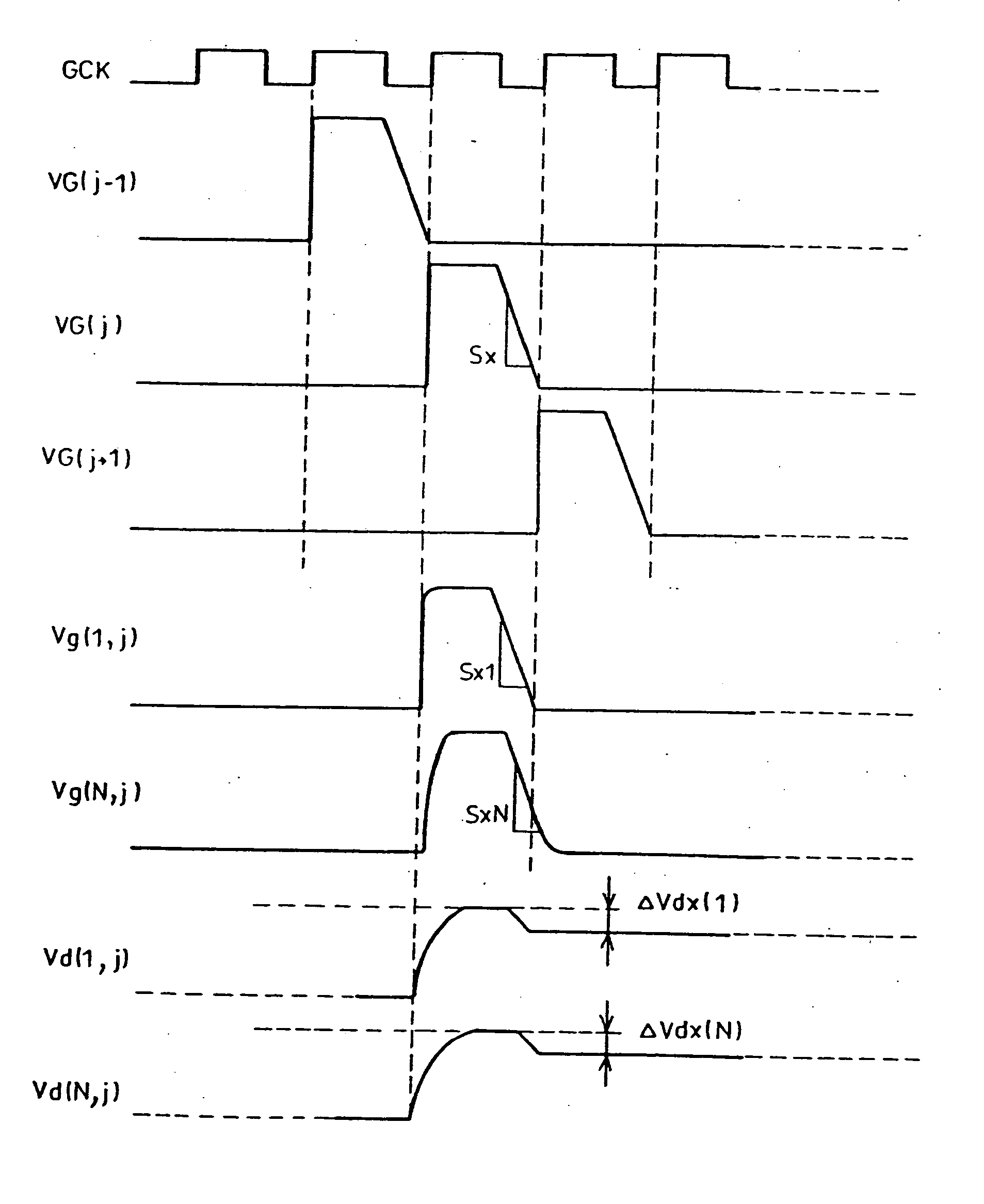
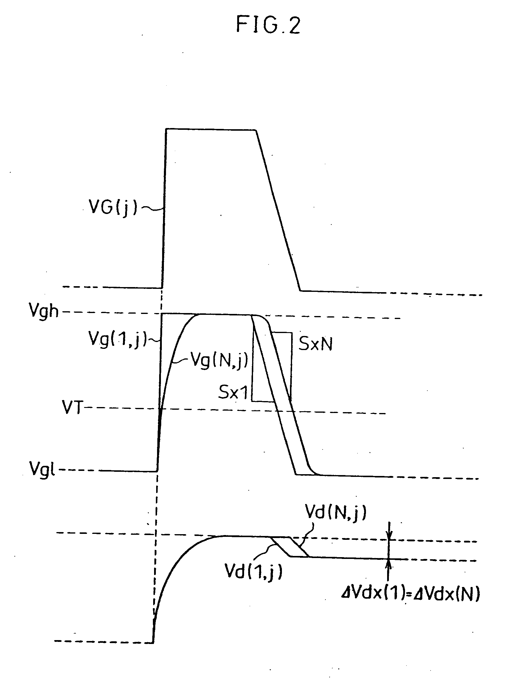
[0047] The following description will explain a first embodiment of the present invention while referring to FIGS. 1 and 2. Note that in FIG. 1 GCK represents a clock signal.
[0048]FIGS. 1 and 2 show output waveforms VG(j−1), VG(j), and VG(j+1) of a scanning signal line driving circuit in accordance with the present embodiment, a scanning signal line waveform Vg(1, j) in the vicinity of an input-side end of a scanning signal line, a scanning signal line waveform Vg(N, j) in the vicinity of the other end of the scanning signal line, and respective pixel potentials Vd(1, j) and Vd(N, j) in the vicinity of the foregoing ends of the scanning signal line. In the output waveform VG(j) of the scanning signal line driving circuit, the fall from a scanning voltage Vgh to a non-scanning voltage Vgl is a fall at a slope (inclination) indicated by a change rate Sx, which is a change quantity per unit time, as shown in FIG. 1.
[0049] The present embodiment has a display system in which data sign...
second embodiment
[0059] The following description will explain a second embodiment of the present invention, while referring to FIG. 3. For conveniences' sake, the members having the same structure (function) as those in FIG. 10 will be designated by the same reference numerals.
[0060] In the second embodiment of the present invention, as shown in FIG. 3, as in the case of the conventional scanning signal line driving circuit shown in FIG. 10, the scanning signal line driving circuit is composed of a shift register section 3a composed of M flip-flops (F1, F2, . . . , Fj, . . . , FM) cascaded, and selection switches 3b which are opened / closed in accordance with outputs from the flip-flops, respectively. An input terminal VD1 out of two input terminals of each selection switch 3b is supplied with a gate-on voltage Vgh which is enough to cause the TFT to attain an ON state, while the other input terminal VD2 thereof is supplied with a gate-off voltage Vgl which is enough to cause the TFT to attain an O...
third embodiment
[0066] As to the above-described second embodiment, a case where the slew-rate control element SC for controlling the fall speed (slope) of the scanning signal is added to the conventional structure of the scanning signal line driving circuit (gate driver) is explained. In this case, however, it is necessary to additionally provide the slew-rate control element SC in the gate driver, and the conventional common inexpensive gate driver cannot be applied as it is. Therefore, it is not economical.
[0067] In the third embodiment of the present invention, a conventional inexpensive common gate driver is used. This case will be explained below, with reference to FIGS. 4 and 5.
[0068] The conventional gate driver is, as explained above with reference to FIG. 10, arranged as follows: the gate-on voltage Vgh and the gate-off voltage Vgl are supplied thereto, and in response to the clock signal GCK, the gate driver outputs the scanning ON voltage Vgh to the scanning signal lines 105 sequentia...
PUM
| Property | Measurement | Unit |
|---|---|---|
| voltage | aaaaa | aaaaa |
| current | aaaaa | aaaaa |
| non-scanning voltage | aaaaa | aaaaa |
Abstract
Description
Claims
Application Information
 - R&D
- Intellectual Property
- Life Sciences
- Materials
- Tech Scout
- Unparalleled Data Quality
- Higher Quality Content
- 60% Fewer Hallucinations
Browse by: Latest US Patents, China's latest patents, Technical Efficacy Thesaurus, Application Domain, Technology Topic, Popular Technical Reports.
© 2025 PatSnap. All rights reserved.Legal|Privacy policy|Modern Slavery Act Transparency Statement|Sitemap|About US| Contact US: help@patsnap.com


