
Uniformity correction by ablation at different track locations along a tire bead

a technology of tire bead and ablation, which is applied in the direction of program control, instrumentation, static/dynamic balance measurement, etc., can solve the problems of tire non-uniformities, tire non-uniformities are important, and the non-uniformities present in the tire structure produce periodic-varying forces

Active Publication Date: 2012-04-19
MICHELIN & CO CIE GEN DES ESTAB MICHELIN
View PDF8 Cites 39 Cited by
  • Summary
  • Abstract
  • Description
  • Claims
  • Application Information

AI Technical Summary

Problems solved by technology

Conventional tire building methods unfortunately have many opportunities for producing non-uniformities in tires.
During rotation of the tires, non-uniformities present in the tire structure produce periodically-varying forces at the wheel axis.
Tire non-uniformities are important when these force variations are transmitted as noticeable vibrations to the vehicle and vehicle occupants.
Some of the uniformities may be hard to correct during the manufacturing process and so additional correction procedures are needed to correct remaining non-uniformities of cured tires.
Some of the known uniformity correction techniques are limited in their application, for example in precision control and / or in the types of tires that are correctable via such techniques.
For example, low profile tires having reduced sidewall height may be particularly difficult to correct using known uniformity correction techniques.
Known techniques may also be limited in the type of uniformity parameters that are correctable.
Although known technology for uniformity correction has been developed, no design has emerged that generally encompasses all of the desired characteristics as hereafter presented in accordance with the subject technology.

Method used


Image

  • Uniformity correction by ablation at different track locations along a tire bead
  • Uniformity correction by ablation at different track locations along a tire bead
  • Uniformity correction by ablation at different track locations along a tire bead

Examples


example

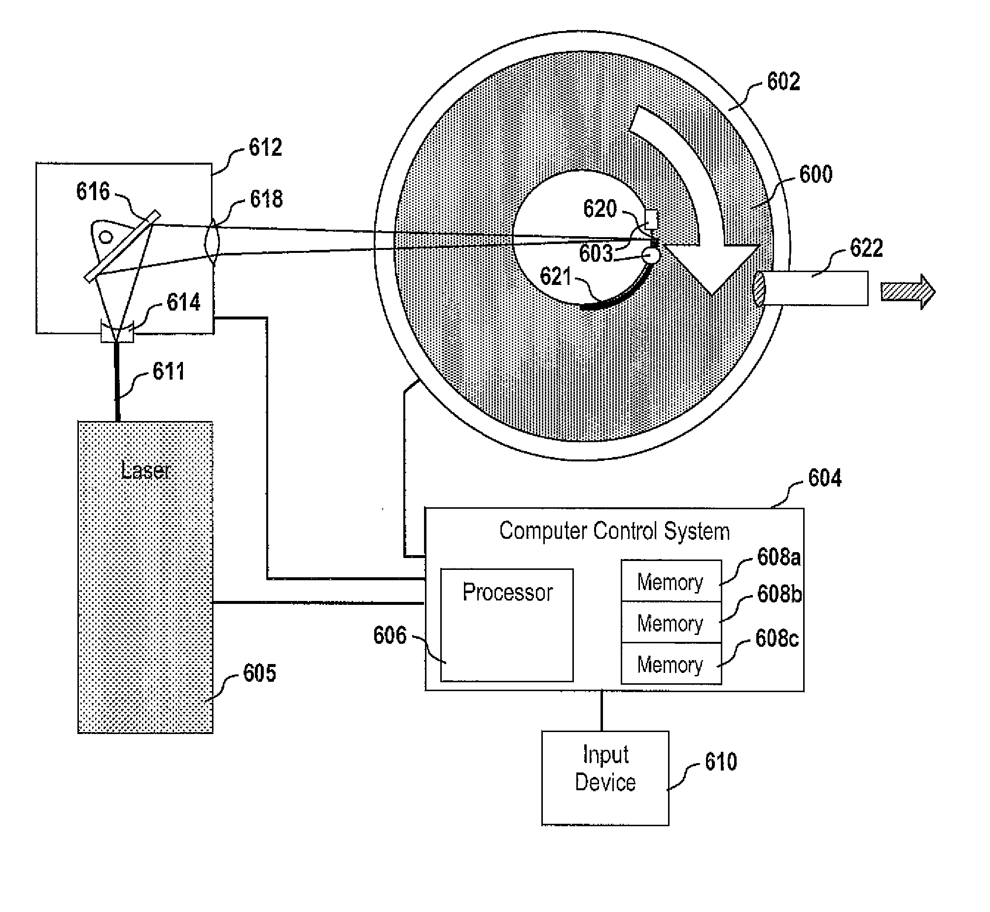
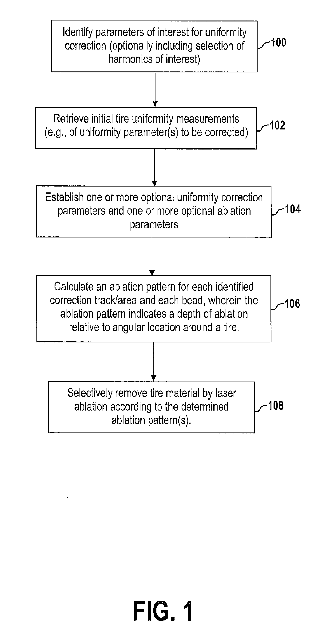
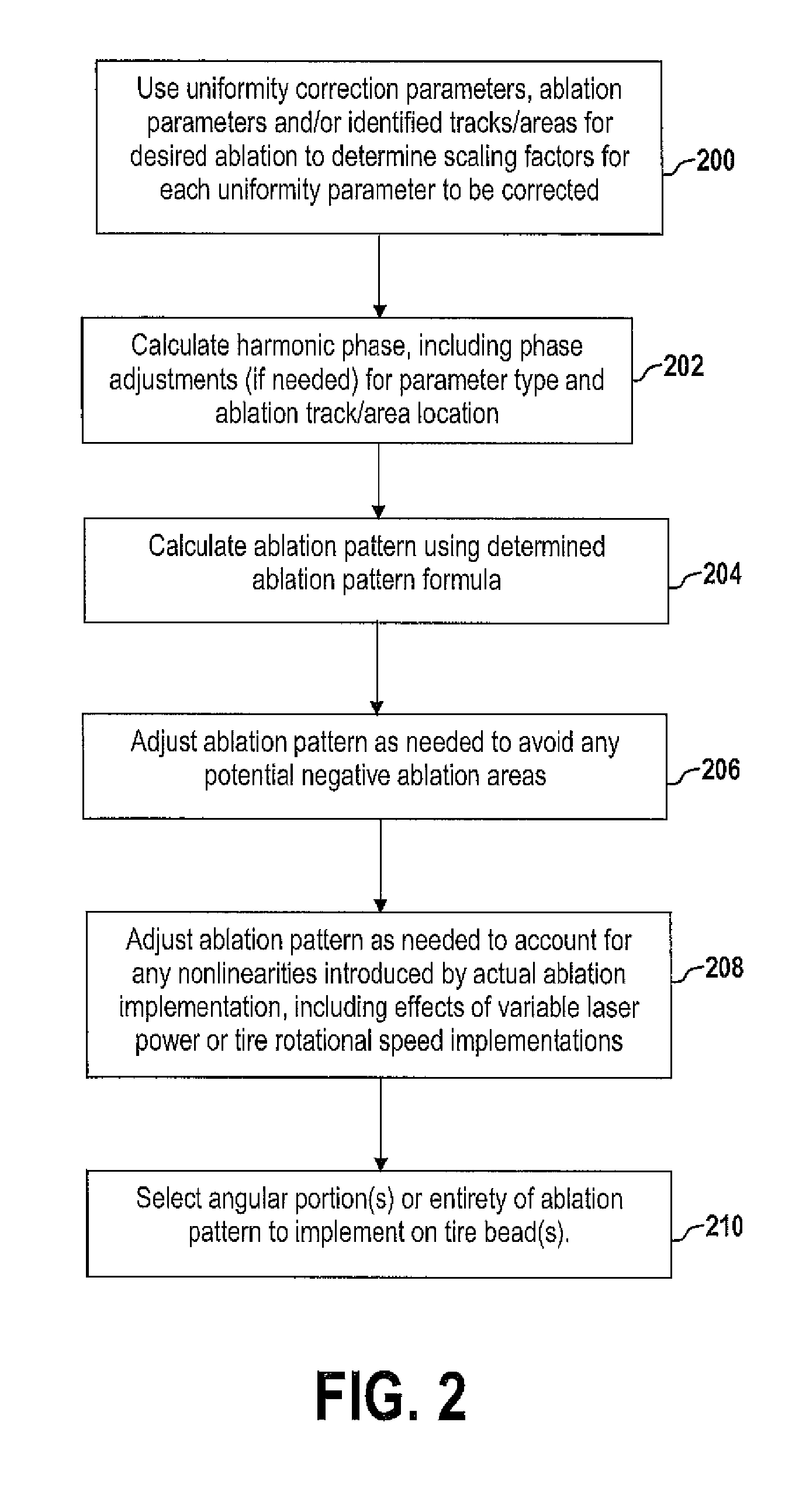
[0096]To better appreciate aspects of the above-described system and method of uniformity correction by bead ablation, an example of multi-harmonic, multi-parameter correction is provided. In the following discussion, as well as the exemplary data shown in FIGS. 13-21, results are shown that compare initial uniformity parameters to corrected ones after the implementation of determined ablation patterns on first and second tire bead locations. The results below provide simulated data (i.e., test results for hypothetical tires), but exemplify the types of improvements in uniformity achieved from applying the subject analysis to actual manufactured tires. The same type of input data available from the following example would be available for actual manufactured tires, and the same ablation pattern determination techniques would be employed.

[0097]Consider a hypothetical test tire having non-uniformity contributions from radial force variation (VR) and lateral force variation (VL). It is...


PUM

PropertyMeasurementUnit
harmonic phaseaaaaaaaaaa
speedaaaaaaaaaa
rotational speedaaaaaaaaaa

Abstract

A system and method for reducing the magnitude of one or more harmonics of one or more uniformity parameters in a cured tire involves selective removal of tire material at one or more track / area locations along first and second bead profiles. Selective removal may occur via ablation at the bead seat, low flange and / or high flange zones to correct for a selected number of harmonics of such parameters as radial, lateral and tangential force variation. Ablation patterns are calculated and implemented on first and second tire beads to achieve desired levels of force reduction at selected angular locations (within the expanse from 0-360 degrees along each tire bead). Ablation patterns may be calculated for implementation at fixed or varied tire rotational speeds and / or fixed or varied levels of laser power.

Description

PRIORITY CLAIM[0001]This application claims priority to U.S. Provisional Patent Application No. 61 / 221,627 filed on Jun. 30, 2009.FIELD OF THE INVENTION[0002]The invention generally relates to systems and methods for improving tire uniformity by selective removal of material along tire bead locations in a cured tire.BACKGROUND OF THE INVENTION[0003]Tire non-uniformity relates to the symmetry (or lack of symmetry) relative to the tire's axis of rotation in certain quantifiable characteristics of a tire. Conventional tire building methods unfortunately have many opportunities for producing non-uniformities in tires. During rotation of the tires, non-uniformities present in the tire structure produce periodically-varying forces at the wheel axis. Tire non-uniformities are important when these force variations are transmitted as noticeable vibrations to the vehicle and vehicle occupants. These forces are transmitted through the suspension of the vehicle and may be felt in the seats and ...

Claims


Application Information

Patent Timeline
Patent Type & Authority Applications(United States)
IPC IPC(8): G06F19/00
CPCG01M17/024B29D30/0061B29D30/0633B29D2030/0635B29D2030/0638B23K26/361G01M1/34Y02P70/10G01M17/02B23K26/03G05B19/41875G05B2219/32177
Inventor HAIR, JR., CLARENCE VERNONNICHOLAS, VERNER STEVEROUSSEAU, JEAN-BAPTISLESTONE, JAMES EDWARD
Owner MICHELIN & CO CIE GEN DES ESTAB MICHELIN
Learn More