
Method and Apparatus for Inducing Therapeutic Hypothermia

Inactive Publication Date: 2012-04-19
VELOMEDIX
View PDF0 Cites 71 Cited by
  • Summary
  • Abstract
  • Description
  • Claims
  • Application Information

AI Technical Summary

Benefits of technology

[0046]In another embodiment, a method for inducing hypothermia in a patient comprises infusing a first volume of hypothermic fluid into a cavity of the patient at a rate of infusion, upon delivering the first volume of hypothermic fluid into the cavity, extracting the hypothermic fluid from the cavity at a rate of extraction, the rate of extraction being larger than the rate of infusion, and stopping or slowing the extraction of fluid from the cavity when a predetermined volume of fluid remains in the cavity.
[0081]In one embodiment, if the second cooling rate of step c) is below a desired rate, increasing the cooling rate.
[0088]In some embodiments, a rate of warming is controlled to a specified rate of warming. In one embodiment, if the patient is warming too quickly, a cooler hyperthermic solution is circulated in the patient cavity to arrest a warming rate. In another embodiment, if the patient is warming too slowly, a warmer hyperthermic solution is circulated in the patient cavity to increase a warming rate. In some embodiments, if the patient is warming too quickly, a pump rate of hyperthermic solution can be lowered to arrest a warming rate. In other embodiments, if the patient is warming too slowly, a pump rate of hyperthermic solution can be increased to increase a warming rate.

Problems solved by technology

Both of these limitations, initiation of and depth of cooling, have made practical application of the technology quite challenging particularly in an ambulance or other emergency settings in the field.
Initiation of cooling, for example, is a major issue since most technologies require sophisticated machinery that would be difficult to place in ambulance so the patient, at best, receives the hypothermic benefit some time after they reach the hospital.
Of the technologies that can be initiated in the field, though, such as cooling blankets, cooling caps, etc., the depth of cooling is a major issue due to surface area limitations, complications (such as intense shivering response) and patient access issues (once the blanket is on, it may be difficult to access the patient).

Method used


Image

  • Method and Apparatus for Inducing Therapeutic Hypothermia
  • Method and Apparatus for Inducing Therapeutic Hypothermia
  • Method and Apparatus for Inducing Therapeutic Hypothermia

Examples


Embodiment Construction

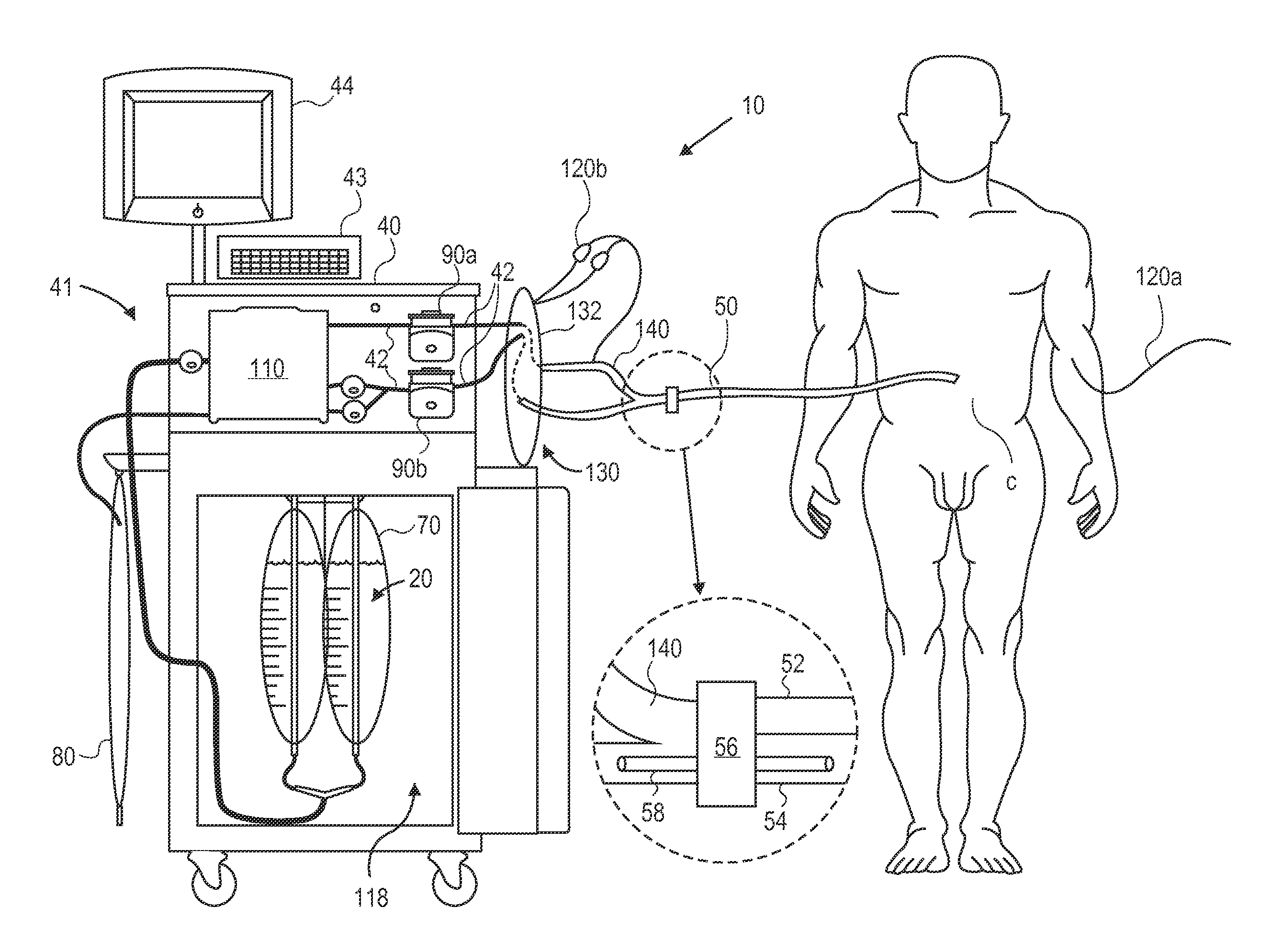
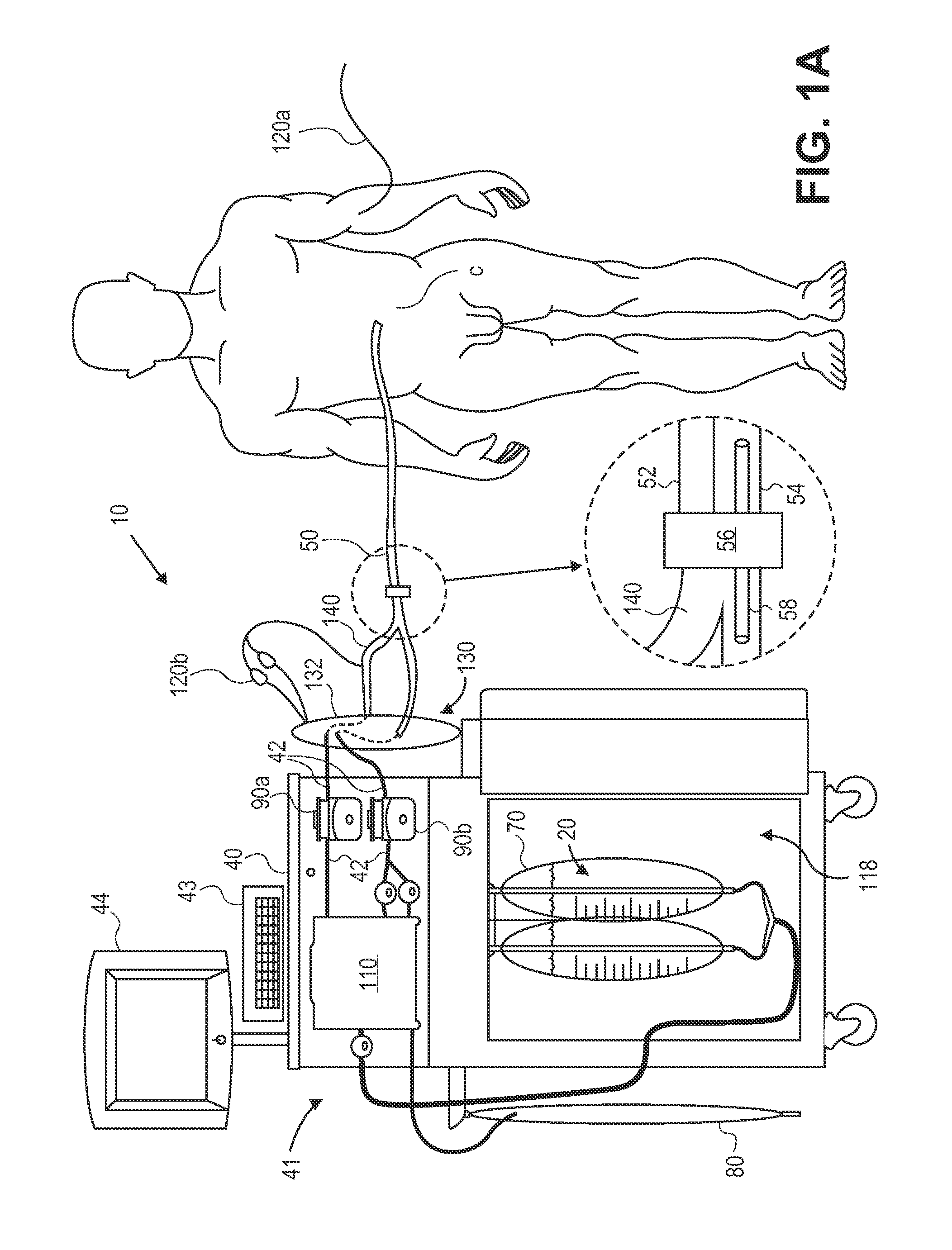
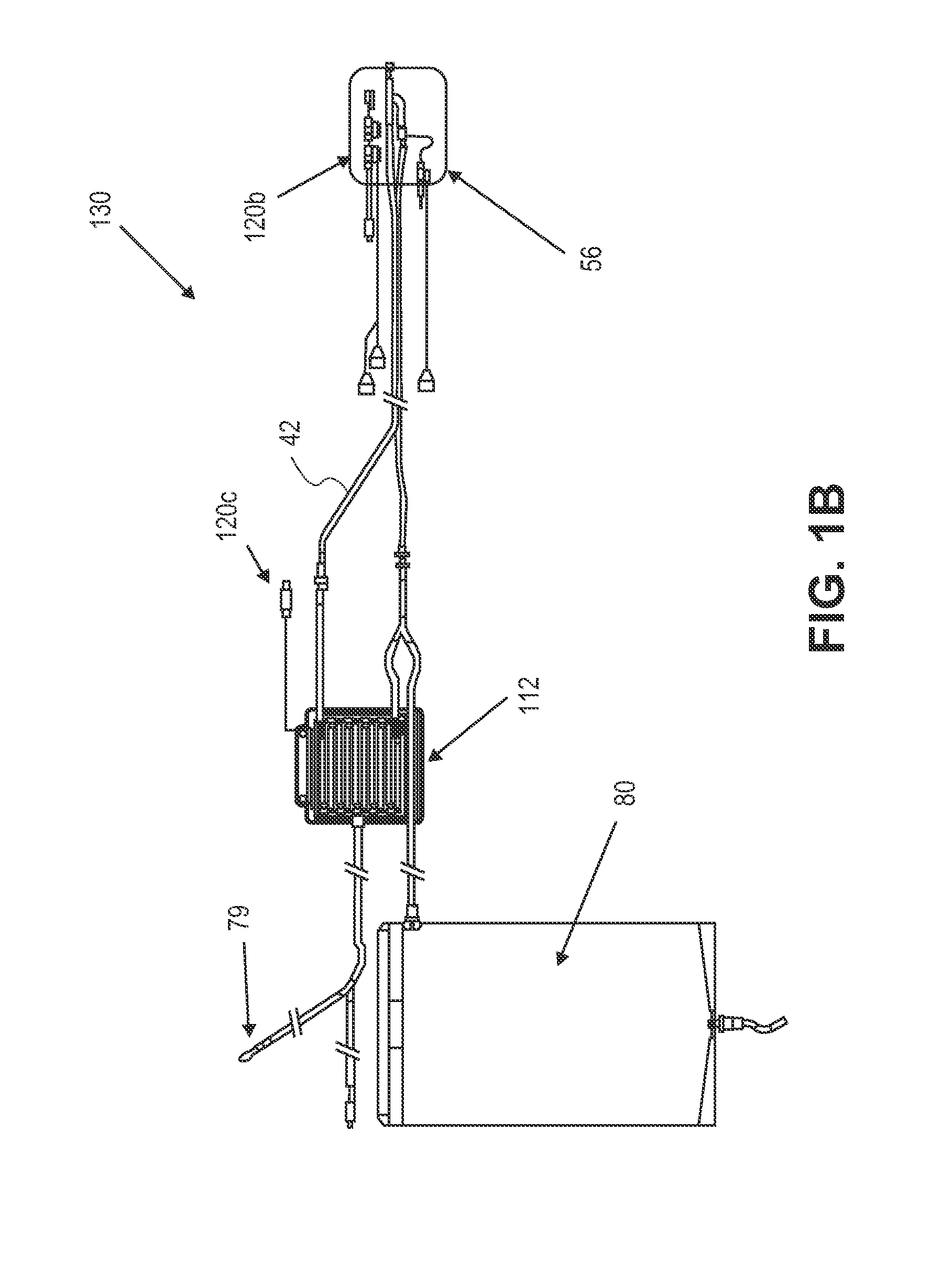
[0100]FIGS. 1A-1B illustrate an embodiment of a system 10 for the delivery of hypothermic or other fluid 20 to a peritoneal or other tissue cavity C. The system can comprise a main unit 40, controller 41, a catheter 50, an access device 60 (shown in FIGS. 2A-2B), a fluid source or fluid reservoir 70, a waste fluid container 80, a pumps 90a and 90b, a heat exchanger assembly 110, one or more sensors such as temperature sensors 120a or pressure sensors 120b, and a Lavage Administration Set (LAS) 130 (Shown in more detail in FIG. 1B). In various embodiments, system 10 can be used to deliver fluids to a number of body cavities such as the peritoneal cavity, the pleural cavity, vagina, digestive tract, nasal cavity, cerebrospinal fluid cavity, and like structures, as well as to various vascular structures. Furthermore, a therapeutic or hypothermic fluid can be delivered to the patient cavity to achieve therapeutic hypothermia, post hypothermic warming, hyperthermia, resuscitation, blood ...


PUM


Abstract

Methods and apparatus for delivering therapeutic hypothermia to a patient are provided which may include any number of features. One feature is a hypothermia system comprising a fluid source, a heat exchanger assembly, a catheter in fluid communication with the fluid source, and a pump system configured to infuse hypothermic fluid into a patient cavity and extract hypothermic fluid from the patient cavity. The hypothermia system can infuse and extract fluid automatically from the patient cavity. In one embodiment, the patient cavity is a peritoneal cavity. A safe access device to gain access to the patient cavity is also provided.

Description

CROSS REFERENCE TO RELATED APPLICATIONS[0001]This application is a continuation-in-part of pending U.S. application Ser. No. 12 / 702,165, filed Feb. 8, 2010, titled “Method and Apparatus for Inducing Therapeutic Hypothermia”.[0002]This application also claims the benefit under 35 U.S.C. 119 of U.S. Provisional Patent Application No. 61 / 393,794, filed Oct. 15, 2010, titled “Hypothermia Catheter and System”, and U.S. Provisional Patent Application No. 61 / 450,067, filed Mar. 7, 2011, titled “Hypothermia Devices and Methods”. These applications are herein incorporated by reference in their entirety.INCORPORATION BY REFERENCE[0003]All publications and patent applications mentioned in this specification are herein incorporated by reference to the same extent as if each individual publication or patent application was specifically and individually indicated to be incorporated by reference.FIELD OF THE INVENTION[0004]The present invention relates generally to medical / surgical devices and met...

Claims


Application Information

Patent Timeline
IPC IPC(8): A61F7/12
CPCA61F7/12A61F2007/0063A61F2007/0069A61F2007/0076A61M1/288A61F2007/0093A61F2007/126A61M1/28A61M2205/3606A61F2007/0078A61M1/285A61M1/32A61M1/166
Inventor HALL, GREGORY W.BURNETT, DANIEL ROGERSSEIDMAN, DANIEL P.
Owner VELOMEDIX
Learn More