Living body state monitor apparatus
a monitor and living body technology, applied in the field of living body state monitors, can solve the problems of not being able to accurately determine the danger of the user's living body state, and the influence of the conventional system,
- Summary
- Abstract
- Description
- Claims
- Application Information
AI Technical Summary
Benefits of technology
Problems solved by technology
Method used
Image

Examples
first embodiment
[0028]1. Configuration of Living Body State Monitor Apparatus 1
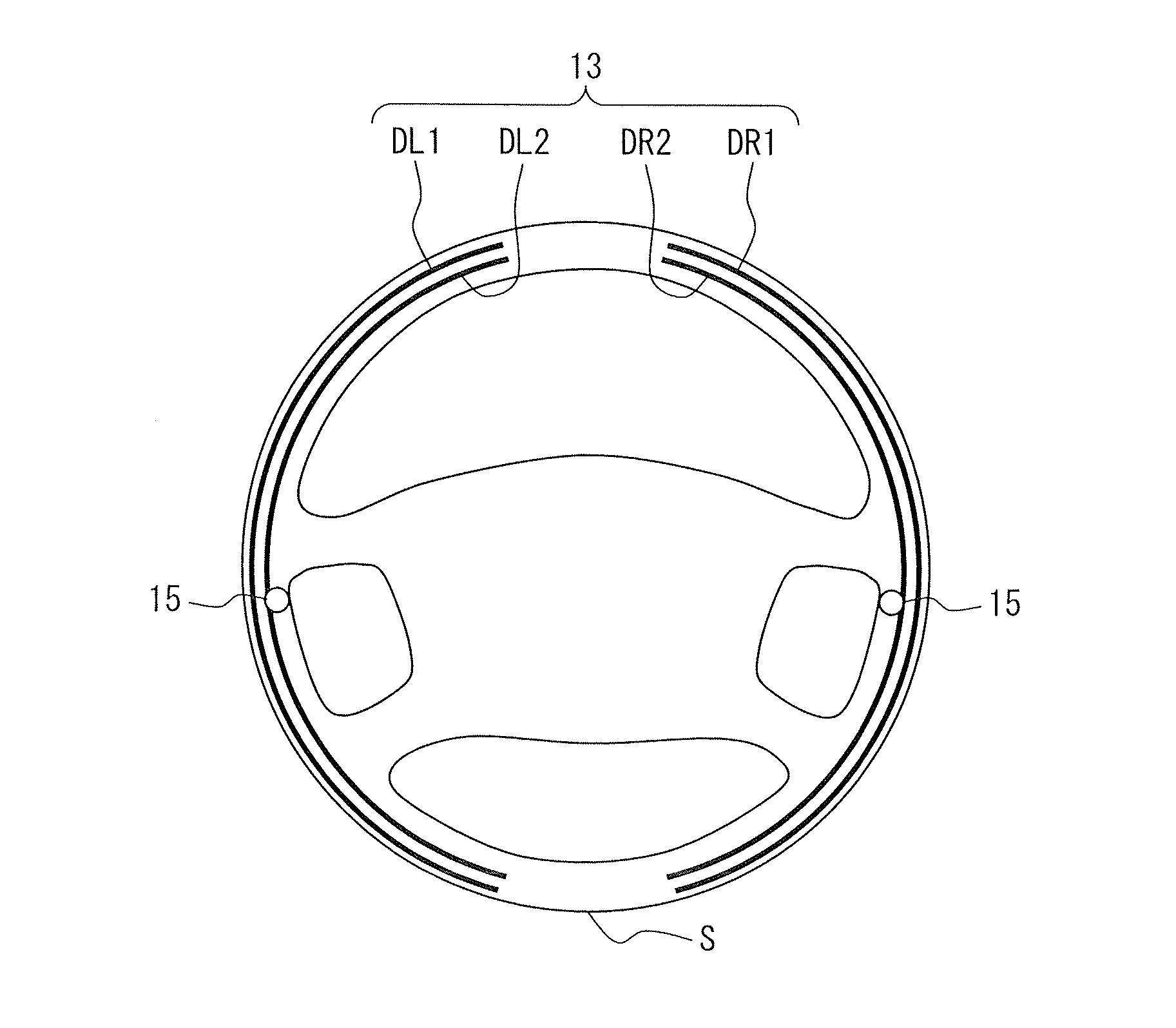
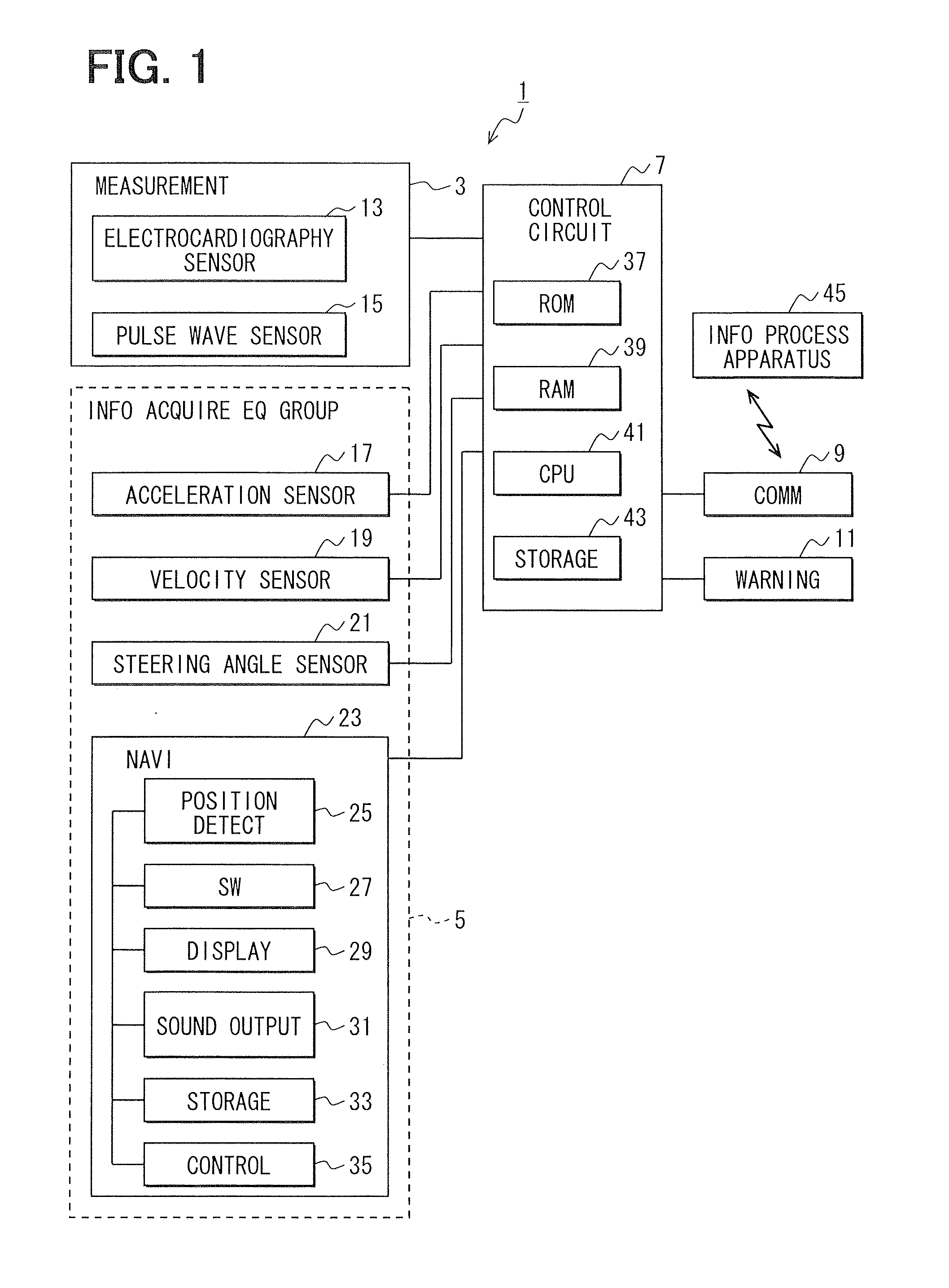
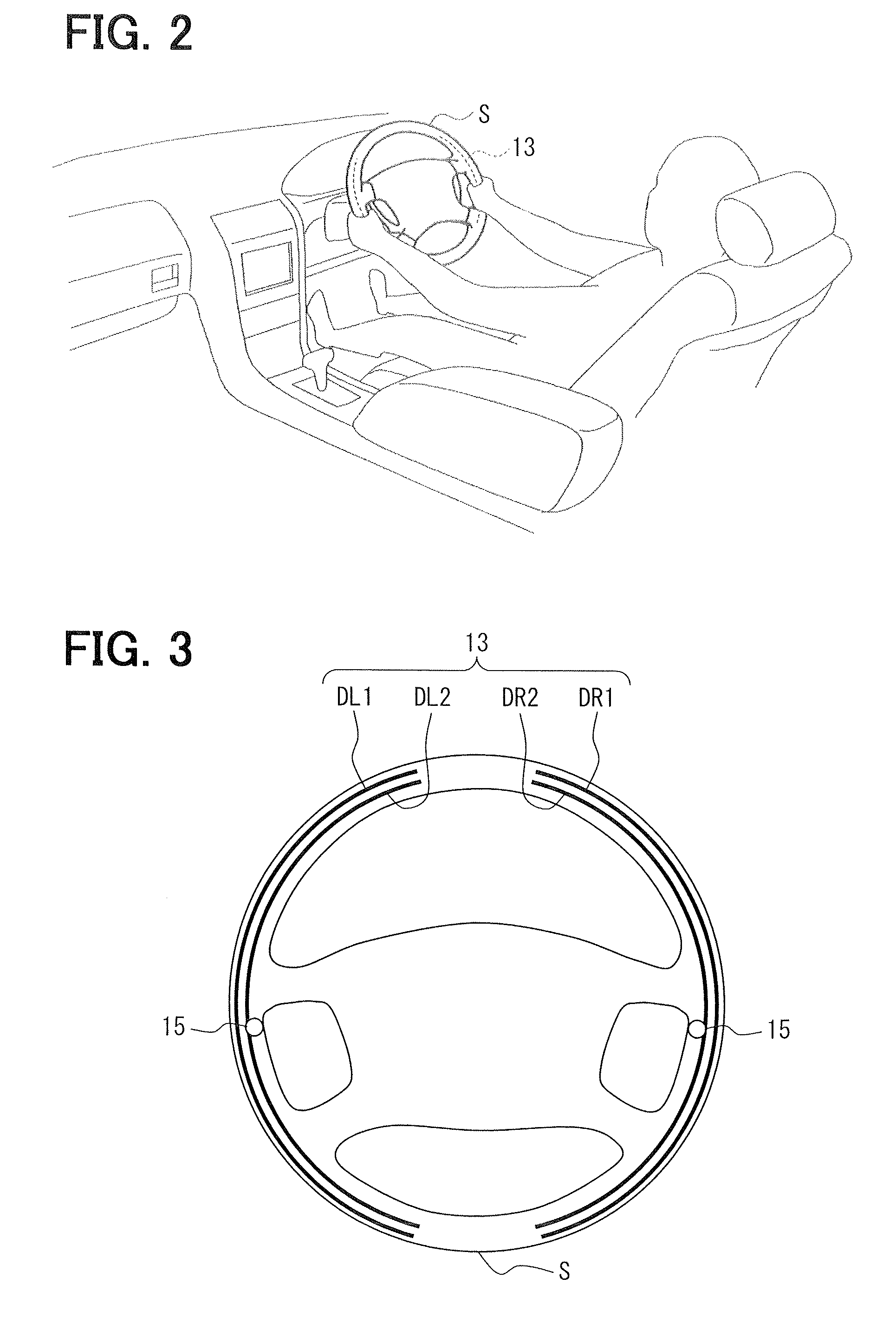
[0029]Based on FIGS. 1 to 3, a configuration of a living body state monitor apparatus 1 will be explained. FIG. 1 is a block diagram illustrating a schematic configuration of a living body state monitor apparatus 1 mounted in a subject vehicle and its peripheral equipment. FIG. 2 is a diagram for explaining a measurement device 3 arranged in a vehicular compartment of the subject vehicle. FIG. 2 is a diagram for explaining the measurement device 3 arranged in a steering wheel S of the subject vehicle.
[0030]The living body state monitor apparatus 1 includes the following: a measurement device 3 (i.e., a living body information acquisition device 3) which acquires living body information that contains an electrocardiography waveform and a pulse wave from a driver (i.e., a living body of the driver) of the subject vehicle; an information acquisition equipment group 5 (i.e., a driving information acquisition device 5) which ...
second embodiment
[0058]The living body state monitor apparatus 1 in a second embodiment has a configuration similar to that of the first embodiment; processes to be executed are partially different from those of the first embodiment. Thus the following mainly explains such a different point while explanation of the same portion as that of the first embodiment is omitted or simplified.
[0059]The process which the living body state monitor apparatus 1 (in particular, the control circuit 7) executes is explained with reference to FIG. 11. The process is started when an ignition signal of the subject vehicle is inputted into the living body state monitor apparatus 1, and, further, executed repeatedly every predetermined time interval.
[0060]S310 to S340 are the same as S10 to S40 in the first embodiment, respectively. At S350, a danger degree of a pulse wave corresponding to an irregular heartbeat is calculated. The danger degree pul(x) on pulse wave is expressed by the following formula (I).
pul(x)=α×f1(x...
third embodiment
[0097]The living body state monitor apparatus 1 in a third embodiment has a configuration similar to that of the first embodiment; a process to be executed is partially different from that of the first embodiment. Thus the following mainly explains such a different point while explanation of the same portion as that of the first embodiment is omitted or simplified.
[0098]The process which the living body state monitor apparatus 1 (in particular, the control circuit 7) executes is explained with reference to FIG. 13. The process is started when an ignition signal of the subject vehicle is inputted into the living body state monitor apparatus 1, and, further, executed repeatedly every predetermined time interval.
[0099]S410 to S420 are the same as S10 to S20 in the first embodiment, respectively. At S430, an irregular heartbeat or irregular heartbeats are invoked which were detected within a past predetermined time period and then stored in the storage device 43. The storage device 43 s...
PUM
 Abstract
Description
Claims
Application Information
 - R&D
- Intellectual Property
- Life Sciences
- Materials
- Tech Scout
- Unparalleled Data Quality
- Higher Quality Content
- 60% Fewer Hallucinations
Browse by: Latest US Patents, China's latest patents, Technical Efficacy Thesaurus, Application Domain, Technology Topic, Popular Technical Reports.
© 2025 PatSnap. All rights reserved.Legal|Privacy policy|Modern Slavery Act Transparency Statement|Sitemap|About US| Contact US: help@patsnap.com