Sheet conveying apparatus and image forming apparatus
a technology of conveying apparatus and sheet metal, which is applied in the direction of electrographic process apparatus, thin material handling, instruments, etc., can solve the problems of limiting further improvement in throughput, and achieve the effect of improving throughput and speed of conveying
- Summary
- Abstract
- Description
- Claims
- Application Information
AI Technical Summary
Benefits of technology
Problems solved by technology
Method used
Image
Examples
first embodiment
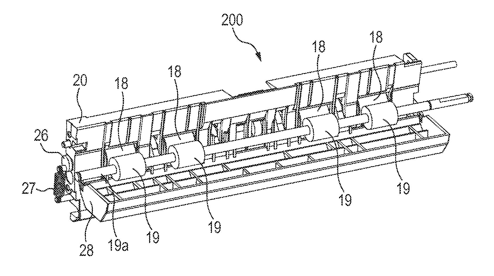
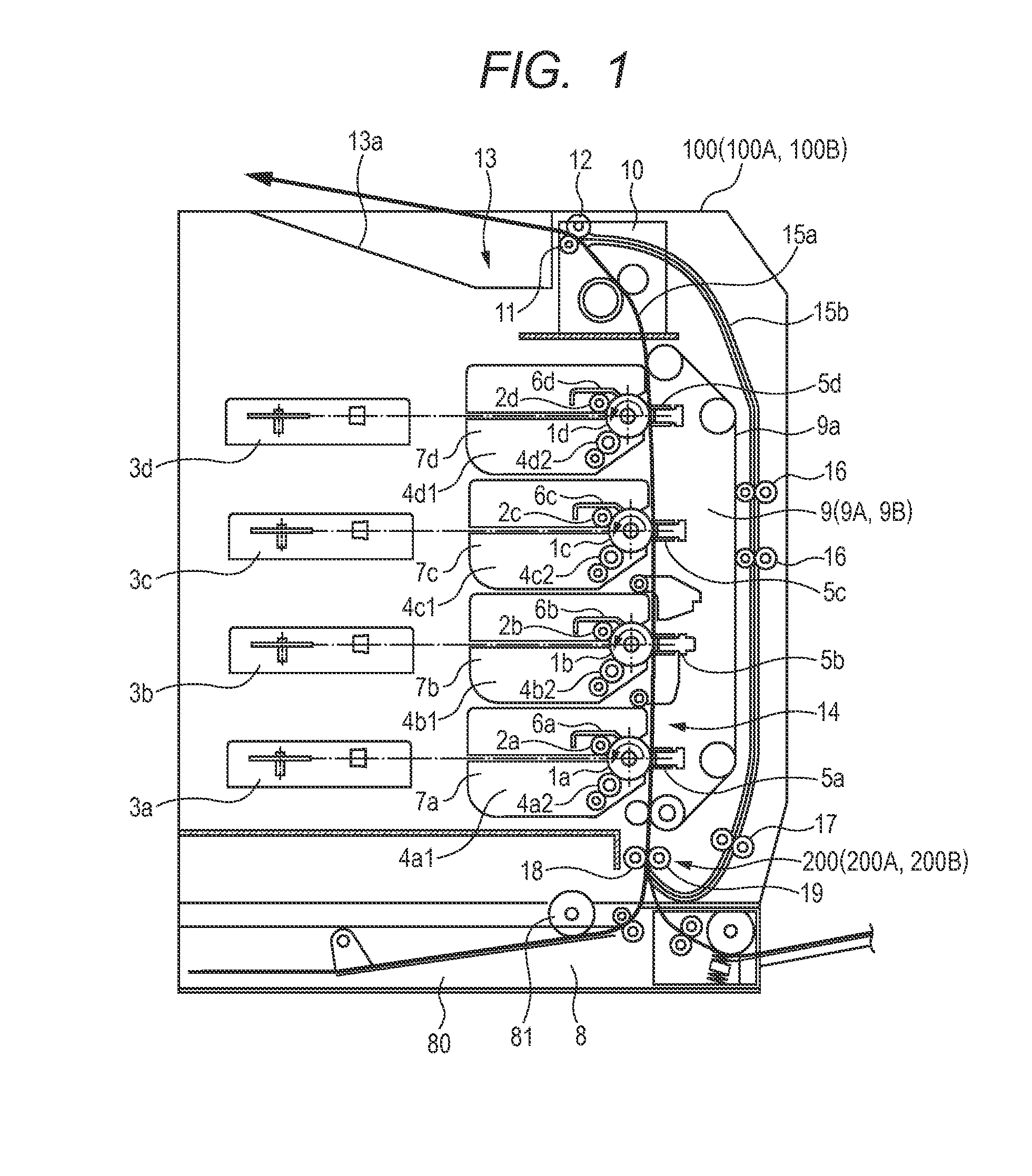
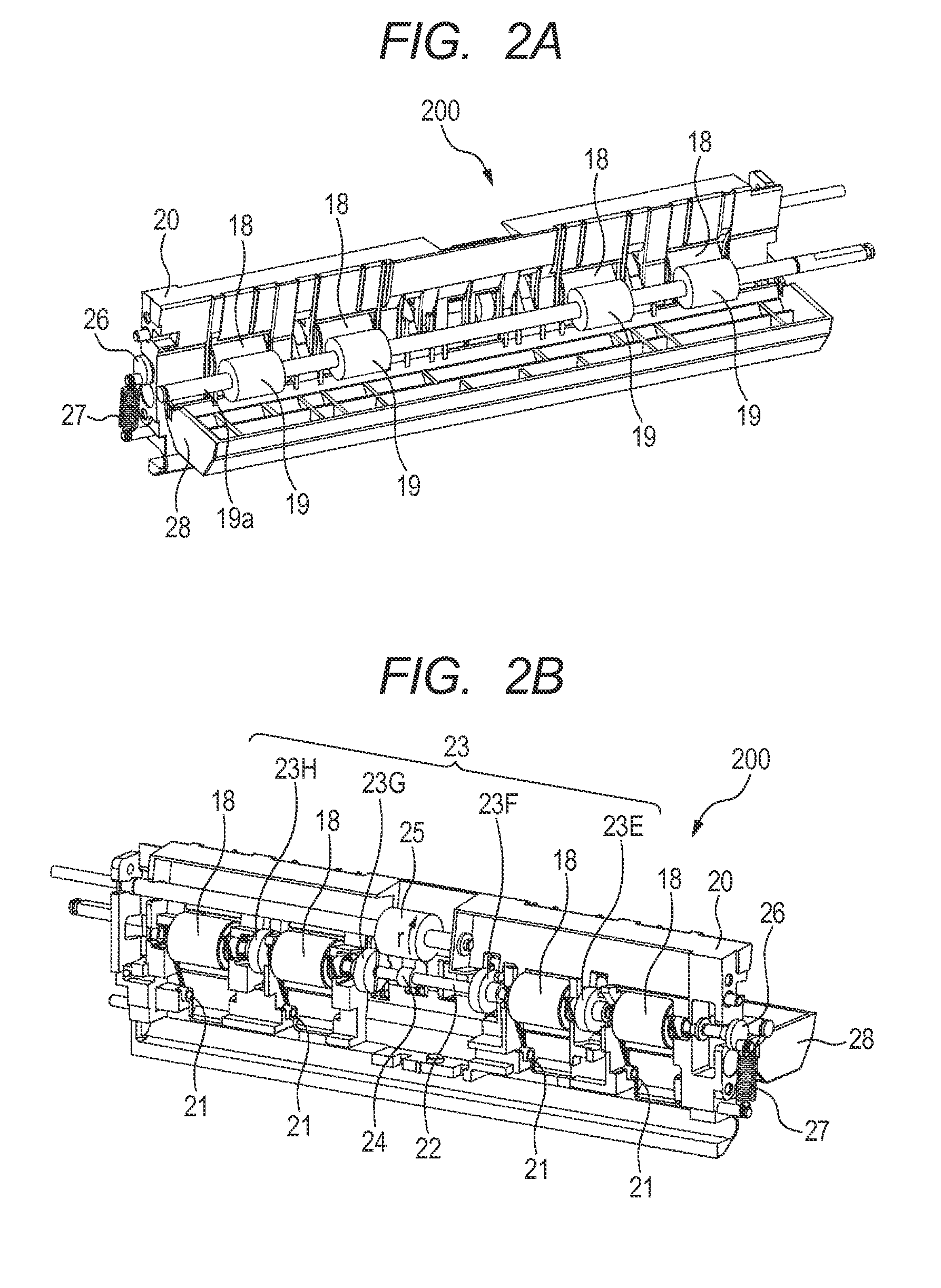
[0053]The image forming apparatus 100 according to a first embodiment of the present invention will be described with reference to FIGS. 1 to 13. An overall structure of the image forming apparatus 100 according to the first embodiment will be described with reference to FIG. 1. FIG. 1 is a sectional view schematically illustrating the overall structure of the image forming apparatus 100 according to the first embodiment of the present invention.
[0054]As illustrated in FIG. 1, the image forming apparatus 100 according to the first embodiment includes a sheet feeding unit 8 adapted to feed sheets S, an image forming unit 14 adapted to form toner images, a fixing unit 10 adapted to fix the toner images transferred in an unfixed state, and a sheet conveying unit 9 serving as a sheet conveying apparatus. Also, the image forming apparatus 100 includes a sheet delivery unit 13 adapted to deliver the sheets S on which the toner images have been fixed.
[0055]The sheet feeding unit 8 includes...
second embodiment
[0099]An image forming apparatus 100A according to a second embodiment of the present invention will be described with reference to FIGS. 14A to 16D and with the aid of FIG. 1. FIG. 14A is a perspective view of a skew correction unit 200A according to the second embodiment, as viewed from the front. FIG. 14B is a perspective view of the skew correction unit 200A illustrated in FIG. 14A, as viewed from the back. FIG. 15A illustrates a state of the shutter spring 27 and shutter drive unit 26 when a sheet S is conveyed to the skew correction unit 200A according to the second embodiment. FIG. 15B illustrates a detection member 34 when a sheet S is conveyed to the skew correction unit 200A according to the second embodiment. FIG. 15C illustrates a state of the assist cam 24 and rotation assist roller 25 when a sheet S is conveyed to the skew correction unit 200A according to the second embodiment. FIG. 15D illustrates a shutter member 23 when a sheet S is conveyed to the skew correction ...
third embodiment
[0111]An image forming apparatus 100B according to a third embodiment of the present invention will be described with reference to FIGS. 17A to 20C and with the aid of FIG. 1. FIG. 17A is a perspective view of a skew correction unit 200B according to the third embodiment, as viewed from the front. FIG. 17B is a perspective view of the skew correction unit 200B illustrated in FIG. 17A, as viewed from the back. FIG. 18A illustrates a state of a shutter cam 326, shutter spring 327, pressing member 335 and cam follower 336 when a sheet S is conveyed to the skew correction unit 200B according to the third embodiment. FIG. 18B illustrates a state of an assist cam 324 and the rotation assist roller 25 when a sheet S is conveyed to the skew correction unit 200B according to the third embodiment. FIG. 18C illustrates a shutter member 323 when a sheet S is conveyed to the skew correction unit 200B according to the third embodiment.
[0112]FIG. 19A illustrates a state of the shutter cam 326, shu...
PUM
 Abstract
Description
Claims
Application Information
 - R&D
- Intellectual Property
- Life Sciences
- Materials
- Tech Scout
- Unparalleled Data Quality
- Higher Quality Content
- 60% Fewer Hallucinations
Browse by: Latest US Patents, China's latest patents, Technical Efficacy Thesaurus, Application Domain, Technology Topic, Popular Technical Reports.
© 2025 PatSnap. All rights reserved.Legal|Privacy policy|Modern Slavery Act Transparency Statement|Sitemap|About US| Contact US: help@patsnap.com


