
Long mission tethered aerostat and method of accomplishing

a technology of aerostats and long missions, applied in the field of lighter thanair airships, can solve the problems of air infiltration, air cannot provide lift, inside the helium bag needs to be purged, etc., and achieve the effect of maintaining the rigidity of the airship

Active Publication Date: 2012-04-19
STRATOCOMM CORP
View PDF19 Cites 33 Cited by
  • Summary
  • Abstract
  • Description
  • Claims
  • Application Information

AI Technical Summary

Benefits of technology

[0021]The invention provides a high altitude tethered aerostat that is capable of replenishing and regulating its internal helium pressure continuously from the ground through a feed-tube that connects the helium or lift gas envelope of the aerostat to a ground reservoir without the need or significantly reducing reliance on ballonets in the airship thereby reducing the demands on blowers and pumping equipment, and methods for operating the same.
[0022]The feed-tube of the invention is sized to support a bidirectional continuous stream of helium gas at a relatively slow flow speed without excessive pumping pressure. The diameter of the feed-tube is constructed to provide just enough helium flow rate to compensate for diurnal variations and helium loss through leakage. The diameter of the feed tube is thus engineered to match the volume of lift gas in the aerostat. In an alternative embodiment the diameter of the feed tube may be chosen to provide high enough helium flow rate that is fast enough to overcome the diurnal and seasonal fluctuation of helium pressure.
[0027]The novel tether novel slip rings and ground based lift gas replenishment, maintenance and purification system allows the novel airship to be deployed for longer durations than the normal around 20 day period of deployment of the prior art aerostats. The novel aerostat of the invention includes a bidirectional valving system that allows the removal of lift gas during daylight periods of heating supplemented by optional ballonets that are filled to maintain the rigidity of the airship and that allow the replenishment of refurbished lift gas at night and the deflation of the optional ballonets at night or combinations thereof as a result of temperature and pressure variations.

Problems solved by technology

In addition to helium leakage, there is also the issue of air infiltration which occurs at a slower rate.
Since air can not provide lift, the air inside the helium bag needs to be purged periodically.
However to remove the air while the airship is aloft for the purpose of extending the mission duration is highly unattractive due to the additional weight, power requirements, and complexity, hence helium scrubbing is usually done on the ground.
The known prior art does not provide for the maintenance of the lift gas on the ground while the airship is deployed by providing the bidirectional transfer of the lift gas between the ground and the aerostat.
The relatively short mission duration and the significant downtime involved in retrieving and re-launching the aerostat, as well as the time it takes to replenish and clean the helium makes it unappealing to use a tethered aerostat for tasks that demand high availability such as weather monitoring and telecommunications.
Frequent launch and retrieval also drastically increase the risk of damaging the envelope of the aerostat, thereby shortening the service life of the entire system.
The use of ballonet to maintain the excess pressure called super-pressure to combat the diurnal pressure fluctuation of the helium gas also produces some unwelcome side effects, the primary of which is the cyclic variation of the lift force resulting from the cyclic expansion and contraction of the helium volume.
Such cyclic variation progressively weakens the tether over time.
In addition, the constant switching of the blower on or off also drastically shortens the service life of the blower.
Malfunction of the blower can cause the aerostat to lose its pressurization resulting in damage to the aerostat by the wind aloft by a sudden increase in wind drag.
Furthermore, ballonets and the attendant blower equipment of the prior art increases the size, weight, and cost of the airship.
This prior art does not provide a bidirectional flow of lift gas or do maintenance on the lift gas by scrubbing the lift gas.
In addition such known prior art feed tubes which would have wall thickness sufficient to accommodate high pressure bursts of helium could not be used in airships deployed at 5,000 feet due to weight which would limit the altitude of the airship.
Further the known prior art has not provided for a transfer of lift gas in a weathervaning airship through airtight slip rings.
Such a high flow rate can rapidly heat up the feed-tube and could eventually damage the feed-tube if the flow rate is sustained for a long duration and damage the airtight connection of the slip ring to accommodate weathervaning.
In the prior art the feed tube has to be thick walled in order to withstand the pressure employed to force helium lift gas into the pressurized aerostat which makes the tether too heavy for higher altitude applications.
Even at such a high flow rate, the refilling of the helium would still take a long time.
At higher altitudes, the increased length of the feed-tube increases the flow resistance, which drastically reduces the flow speed, making manual control of the refilling process infeasible.
This dramatically increases the thickness of the feed-tube and since the total weight of the feed-tube is proportional to the thickness as well as the length of the tube, the concomitant increase in the weight of the feed-tube makes such a scheme impractical.
None of the known prior art has a tether with a hollow core surrounded by a strength member having embedded therein electrical cables and optical telecommunications cables that have at each end novel slip rings to enable lift gas to be purified and replenished from the ground.

Method used


Image

  • Long mission tethered aerostat and method of accomplishing
  • Long mission tethered aerostat and method of accomplishing
  • Long mission tethered aerostat and method of accomplishing

Examples


Embodiment Construction

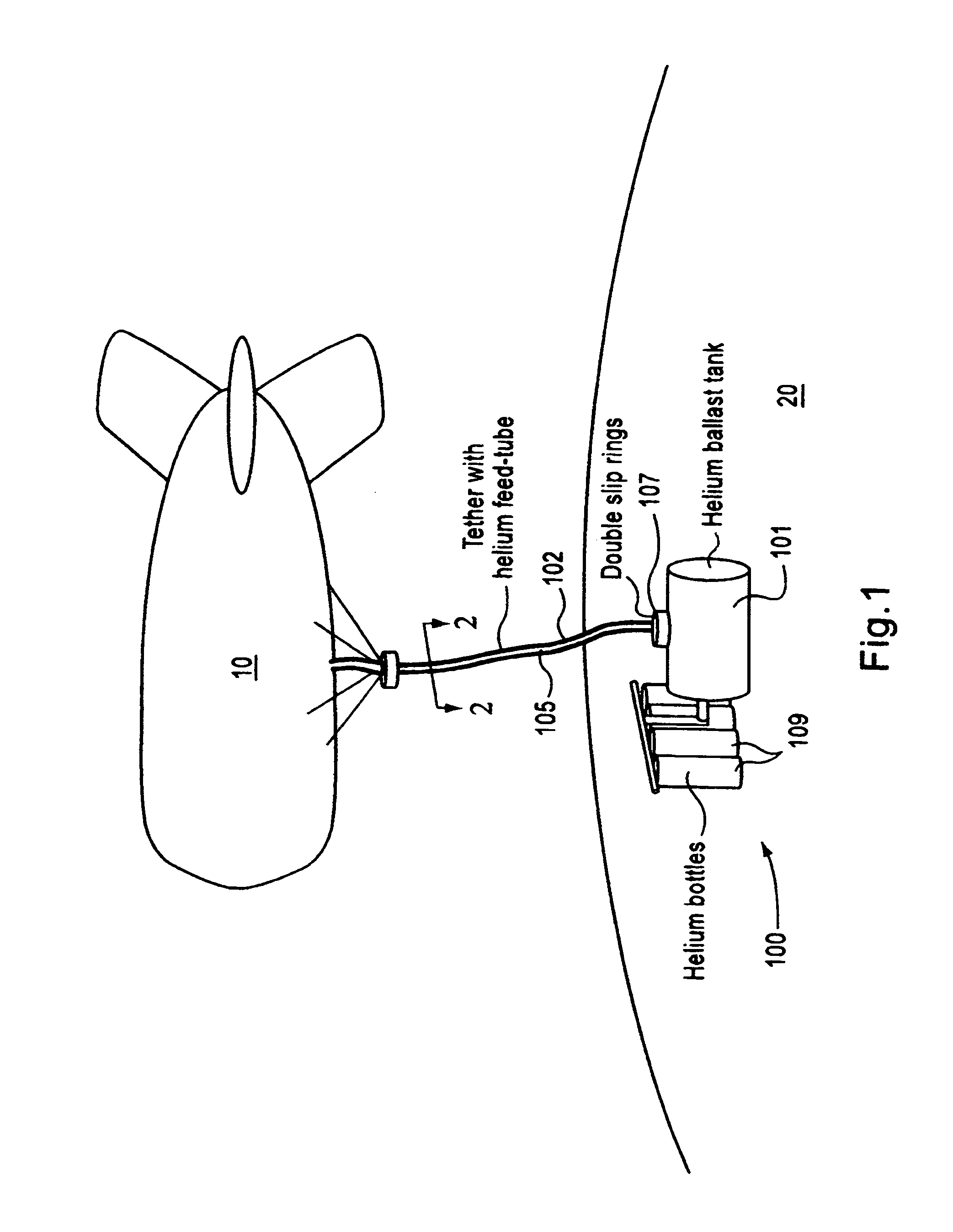
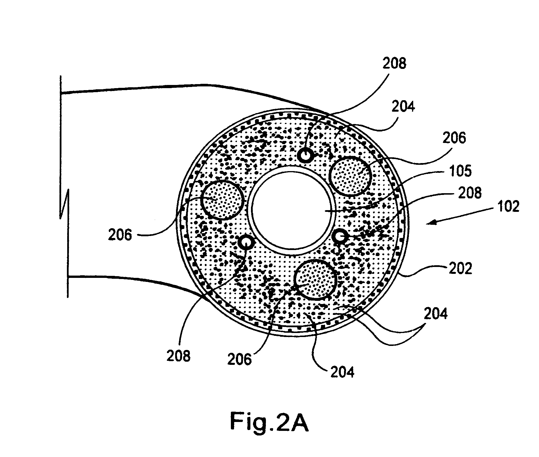
[0038]FIGS. 1 to 4A and 4B illustrate a ground-based helium ballast system for a tethered aerostat 10 formed in accordance with one embodiment of the present invention. Referring to FIG. 1, the ground based ballast system 100 generally comprises a ground based helium ballast tank having an attendant helium storage tank 101 with optional helium storage bottles 109 disposed on the ground 20 including a feed-tube 105 which is either embedded within the tether or runs parallel to the tether 102. A double slip ring 107 allows the helium feed-tube 105 as well as the rest of the tether 102 to adapt to continuous orientation (yaw) and rotational changes of the aerostat and catenary configuration of the tether without losing its helium-tightness. The helium ballast tank 101 and the helium storage bottles 109 may be housed in a launch and retrieval vehicle, not shown, on the ground 20.

[0039]The tethered aerostat 10 is of a suitable aerodynamic shape, as shown in FIG. 1, in order to minimize w...


PUM


Abstract

Apparatus and method for a continuous replenishing of the lift gas and maintaining the proper pressure and lift of a tethered medium altitude aerostat utilizing a novel feed tube running the entire length of the tether. A first end of the feed tube is connected to the aerostat while a second end is connected through a novel slip ring means to a pressure controlled helium ballast chamber and scrubber on the ground to maintain pressure and lift by a reversible compressing pump. A plurality of pressure and temperature sensors and tension gauges strategically placed inside and around the airship continuously monitor the temperature and pressure changes in the aerostat. A data retrieval and communication unit mounted on the aerostat collects measurement data from the pressure, temperature and tension sensors which is relayed to the ground station and the data is used to regulate lifting gas pressure inside the aerostat.

Description

CROSS REFERENCE TO RELATED APPLICATIONS[0001]Not applicable.STATEMENT REGARDING FEDERALLY SPONSORED RESEARCH OR DEVELOPMENT[0002]Not applicable.INCORPORATION-BY-REFERENCE OF MATERIAL SUBMITTED ON COMPACT DISC[0003]Not applicable.REFERENCE TO A “MICROFICHE APPENDIX”[0004]Not applicable.BACKGROUND OF THE INVENTION[0005]1. Field of the Invention[0006]The present invention pertains generally to the field of lighter-than-air airships. More particularly, the invention relates to the control and regulation of a lift gas such as helium along with its pressure within a tethered helium filled aerostat using a ground based lift gas ballast chamber. The invention includes a novel hollow tether with a lifting gas feed tube and novel double slip rings which allow weathervaning by providing a substantially airtight connection between the ground and the aerostat.[0007]2. General Nature Of the Prior Art[0008]A tethered aerostat is an aerodynamic shaped, lighter-than-air vessel of a flexible structur...

Claims


Application Information

Patent Timeline
IPC IPC(8): B64B1/50B64B1/70
CPCB64B1/50B64B1/56D07B1/12B64B1/62
Inventor LEE, YEE-CHUN
Owner STRATOCOMM CORP
Learn More