
Fast and accurate current driver with zero standby current and features for boost and temperature compensation for MRAM write circuit

a write circuit and driver technology, applied in the field of current driver design for write circuits of mram, to achieve the effect of fast and accurate current drivers

Active Publication Date: 2012-04-12
TAIWAN SEMICON MFG CO LTD
View PDF5 Cites 12 Cited by
  • Summary
  • Abstract
  • Description
  • Claims
  • Application Information

AI Technical Summary

Benefits of technology

[0018]A further object of the present invention is to achieve current drivers without requiring stand-by current.

Problems solved by technology

It is a challenge for engineers to design a fast and accurate current driver.

Method used


Image

  • Fast and accurate current driver with zero standby current and features for boost and temperature compensation for MRAM write circuit
  • Fast and accurate current driver with zero standby current and features for boost and temperature compensation for MRAM write circuit
  • Fast and accurate current driver with zero standby current and features for boost and temperature compensation for MRAM write circuit

Examples


Embodiment Construction

[0029]Two preferred embodiments of the present invention to provide fast and accurate current drivers for write circuits in Magnetic Random Access Memories (MRAM) using Magnetic Tunnel Junction (MTJ) are disclosed. The drivers are based on diode or bipolar voltage reference divided by resistors without current or voltage feedback. The invention achieves fast and accurate current output with zero standby current, which was previously not done using current reference and current mirror structures. The boost and temperature compensation features associate with the design also enhance the write performance of MRAM chips.

It should be noted that the invention could be used for other applications / devices that require accurate current drive with zero standby current. It's not limited to MRAM.

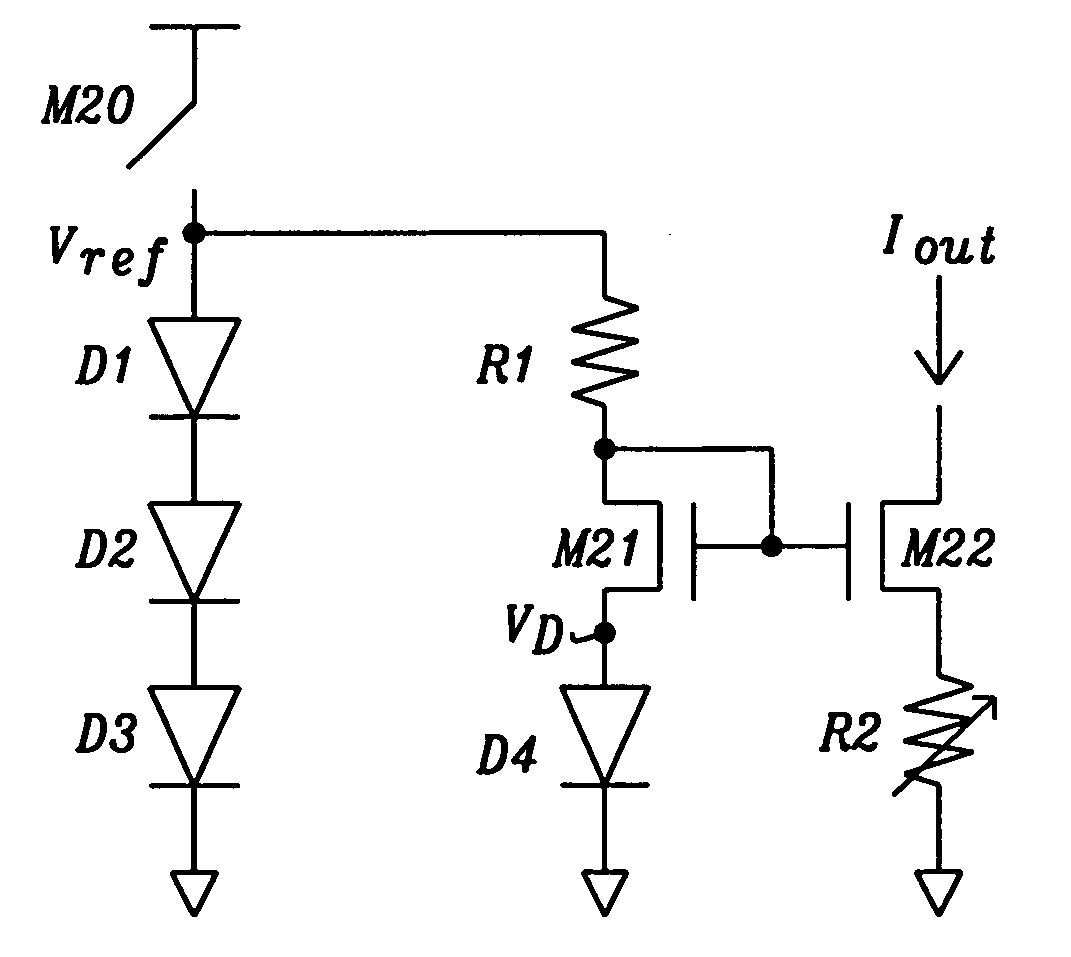
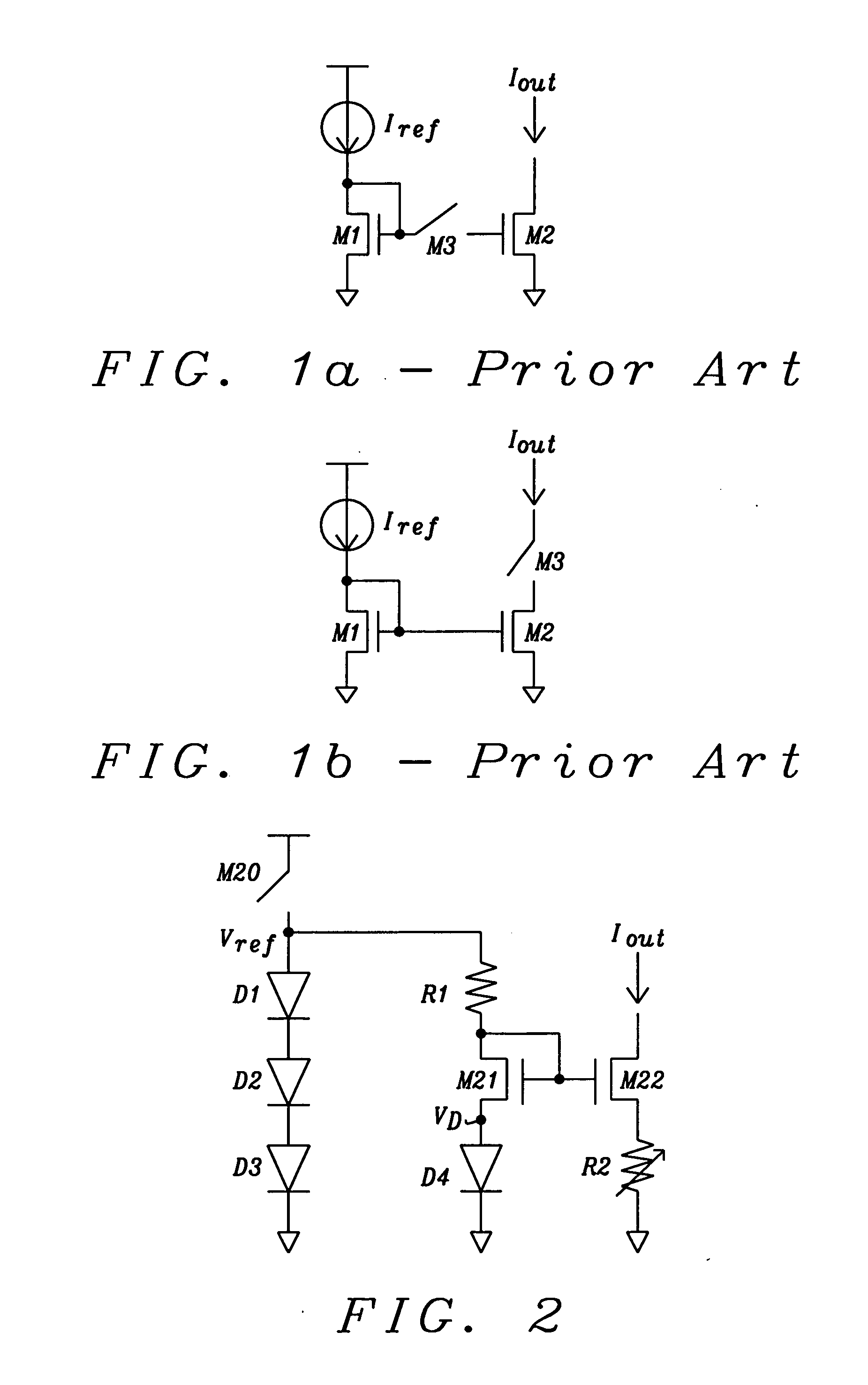
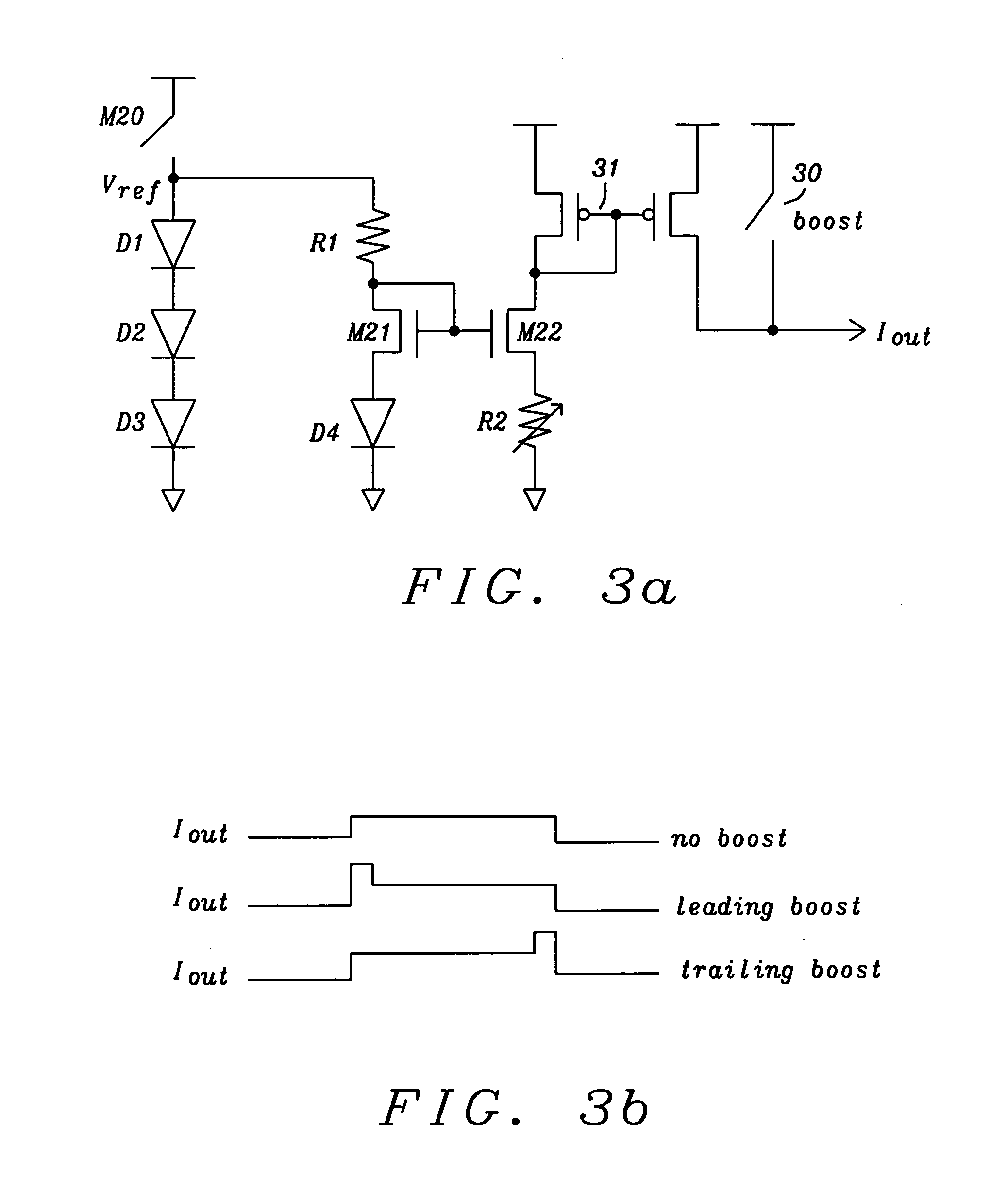
[0030]FIG. 2 shows a circuit invented for a fast and accurate current driver. A switch M20 connecting in a preferred embodiment three diodes D1, D2, and D3 in series generates a reference voltage Vref, ...


PUM


Abstract

Systems and methods for realizing current drivers without current or voltage feedback for devices that require accurate current drive with zero standby current has been disclosed. In a preferred embodiment of the invention this current driver is applied for write circuits for MRAMs. A fast and accurate reference current is generated by diode voltage divided by resistor without any feedback. The diode current is not fed back from the reference current. The diode current is generated from a regulated voltage. Temperature compensation of the write current is inherently built in the diode current reference. Fine-tuning of the temperature coefficient is achieved by mixing poly and diffusion resistors. A switch inserted in the current driver can turn on the driver fast and without a need for standby current. Leading boost in the current driver can fast charge the large coupling capacitance of word and bit lines and speed up write timing.

Description

BACKGROUND[0001](1) Field of the Invention[0002]This invention relates generally to Magnetic Random Access Memories (MRAM) and relates more specifically to current driver design for write circuits of MRAM using Magnet Tunnel Junction (MTJ).[0003](2) Description of the Prior Art[0004]In order to write the MTJ cells in a field MRAM, external magnetic field is applied in the x and y direction parallel to the tunnel junction. In practice, the magnetic field is generated by currents flowing in the word line and the bit line of the memory array. The lower boundary of the current is set to guarantee all MTJ cells can be written (full select requirement), while the upper boundary is set to guarantee that other cells in the same bit line are not written (half select requirement). Therefore, accurate current is required for the bit line or the word line current drivers.[0005]FIG. 1a+b prior art show the conventional way to generate accurate current using current mirrors. It consists of three ...

Claims


Application Information

Patent Timeline
Patent Type & Authority Applications(United States)
IPC IPC(8): H03K3/00
CPCG05F3/26G11C29/028G11C29/021G11C11/16
Inventor YUH, PERNG-FEIWANG, POKANGPU, LEJANTRAN, MINHCHANG
Owner TAIWAN SEMICON MFG CO LTD
Learn More