
Caliper assembly for disc brake system

a disc brake and caliper technology, applied in mechanically actuated brakes, slack adjusters, braking elements, etc., can solve the problems of limited axial clearance between the wheel and the rotor, and cannot be packaged, so as to improve the nvh performance, optimize the component performance, and improve the stiffness of the braking performance

Inactive Publication Date: 2012-04-12
AKEBONO BRAKE
View PDF5 Cites 48 Cited by
  • Summary
  • Abstract
  • Description
  • Claims
  • Application Information

AI Technical Summary

Benefits of technology

[0011]It should be appreciated that the above referenced aspects and examples are non-limiting, as others exist within the present invention, as shown and described herein. The caliper bodies, support brackets, caliper assemblies and disc brake assemblies of the invention exhibit improved NVH performance; provide flexibility in design to allow adjustment of the stiffness of the braking performance to optimize component performance. The invention facilitates achievement of push pull braking function without requiring special brake pad designs and greater flexibility in the design of braking systems. The caliper bodies, caliper assemblies and disc brake systems of the invention allow the utilization of push pull design concepts without the need for a tie bar on the outboard side of a caliper assembly. The brake pads of used in the invention do not require the use of high strength materials for the carrier plate and offer greater flexibility in the selection of friction material for the brake pad.

Problems solved by technology

In some wheel packages, the available axial clearance between the wheel and rotor is limited and does not allow packaging of an outer tie bar on the caliper support.
However, from the functional stiffness / stress aspect of the support bracket / caliper assembly design, an outer tie bar is required.
Brake pads used in existing push pull designs generally require the use of high strength materials for the brake pad carrier plate, such as high strength steel which is difficult to process for conventional manufacturing processes such as stamping.

Method used


Image

  • Caliper assembly for disc brake system
  • Caliper assembly for disc brake system
  • Caliper assembly for disc brake system

Examples


Embodiment Construction

[0023]The explanations and illustrations presented herein are intended to acquaint others skilled in the art with the invention, its principles, and its practical application. Those skilled in the art may adapt and apply the invention in its numerous forms, as may be best suited to the requirements of a particular use. Accordingly, the specific embodiments of the present invention as set forth are not intended as being exhaustive or limiting of the invention. The scope of the invention should, therefore, be determined not with reference to the above description, but should instead be determined with reference to the appended claims, along with the full scope of equivalents to which such claims are entitled. The disclosures of all articles and references, including patent applications and publications, are incorporated by reference for all purposes. Other combinations are also possible as will be gleaned from the following claims, which are also hereby incorporated by reference into ...


PUM


Abstract

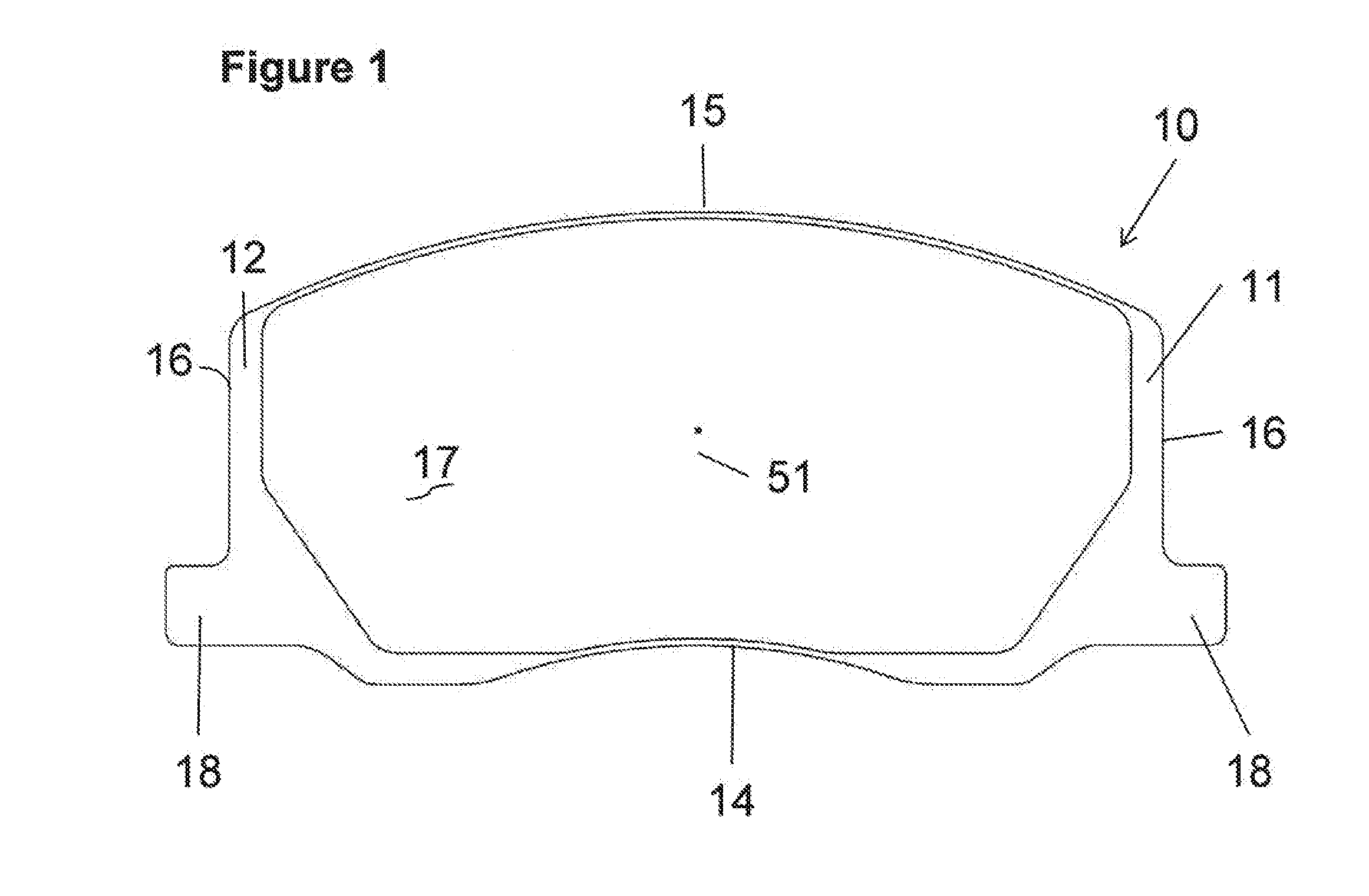
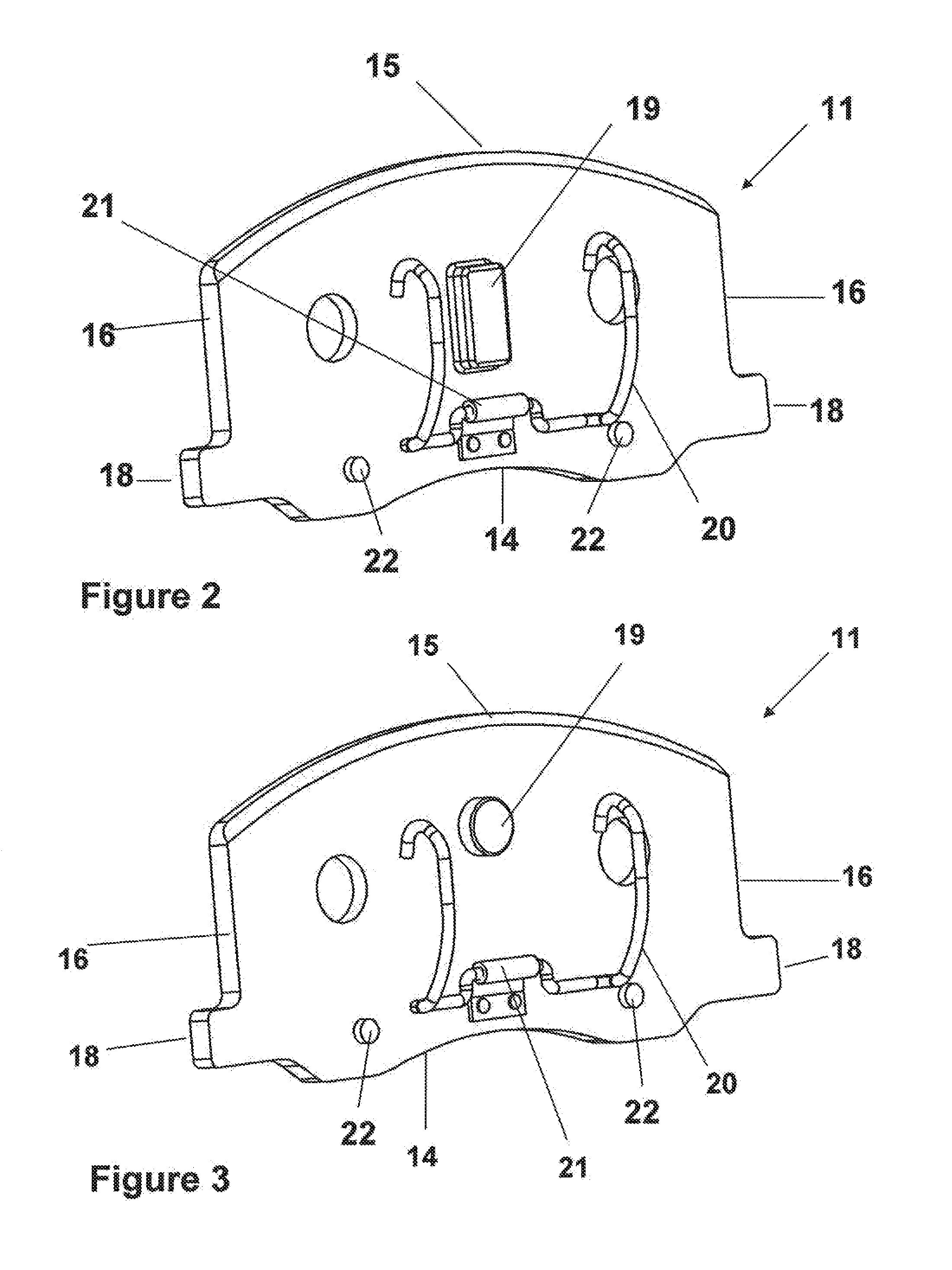
A caliper assembly comprising: a brake pad comprising a carrier plate having two opposing faces and a top edge a bottom edge and two opposing side edges, wherein on one face is friction material and on the opposing face is a projection adapted to seat in a matched hole or recess in a caliper body, the two opposing side edges each having an ear which is adapted to seat in pad locator indentations in a support structure; a support structure comprising a recess for housing at least one brake pad and at least two pad locator indentations adapted for receiving the ears located on the two opposing sides of the brake pad and at least two caliper body locator indentations for seating two ears defined by the caliper body; and a caliper body having a hole or recess adapted for seating the projection on the opposing face of the brake pad and having two ears on each opposing side which are adapted to seat in the caliper body locator indentations of the support structure; wherein the ears of the brake pad are seated in the pad locator indentations of the support structure, the projection on the opposing face of the brake pad is seated in the hole or recess located in the caliper body, and a clip which engages the opposing face of the brake pad and the caliper body and holds the brake pad in position with respect to the caliper body and the ears of the caliper body are seated in the caliper body locator indentations in the support structure.

Description

FIELD OF THE INVENTION[0001]The present invention relates to disc brake caliper assemblies and disc brake assemblies for use in motor vehicles which operate in push pull mode during braking.BACKGROUND[0002]Many motor vehicles are equipped with braking systems to allow operators to control, slow or stop the vehicles when desired. A commonly used braking system is a disc brake system. In general, a disc brake system comprises a caliper assembly and a brake disc. The caliper assembly is secured to a vehicle knuckle or suspension component and the disc is connected to the wheel hub of the vehicle. The disc comprises an annular braking band. The caliper assembly comprises a caliper body which comprises two lateral walls disposed on both sides of the disc which are connected by means of connecting members which straddle the brake disc and further comprises a support structure in the caliper assembly. When the vehicle is in motion the disc passes between the two lateral walls of the calipe...

Claims


Application Information

Patent Timeline
Patent Type & Authority Applications(United States)
IPC IPC(8): F16D55/226F16D65/092
CPCF16D55/227F16D65/092F16D2055/0041F16D65/0979F16D2055/0008F16D65/095
Inventor NARAYANAN V, LAKSHMI
Owner AKEBONO BRAKE
Learn More