
Hub motor for electric vehicles

Inactive Publication Date: 2012-04-05
LO CHIU HSIANG
View PDF6 Cites 54 Cited by
  • Summary
  • Abstract
  • Description
  • Claims
  • Application Information

AI Technical Summary

Benefits of technology

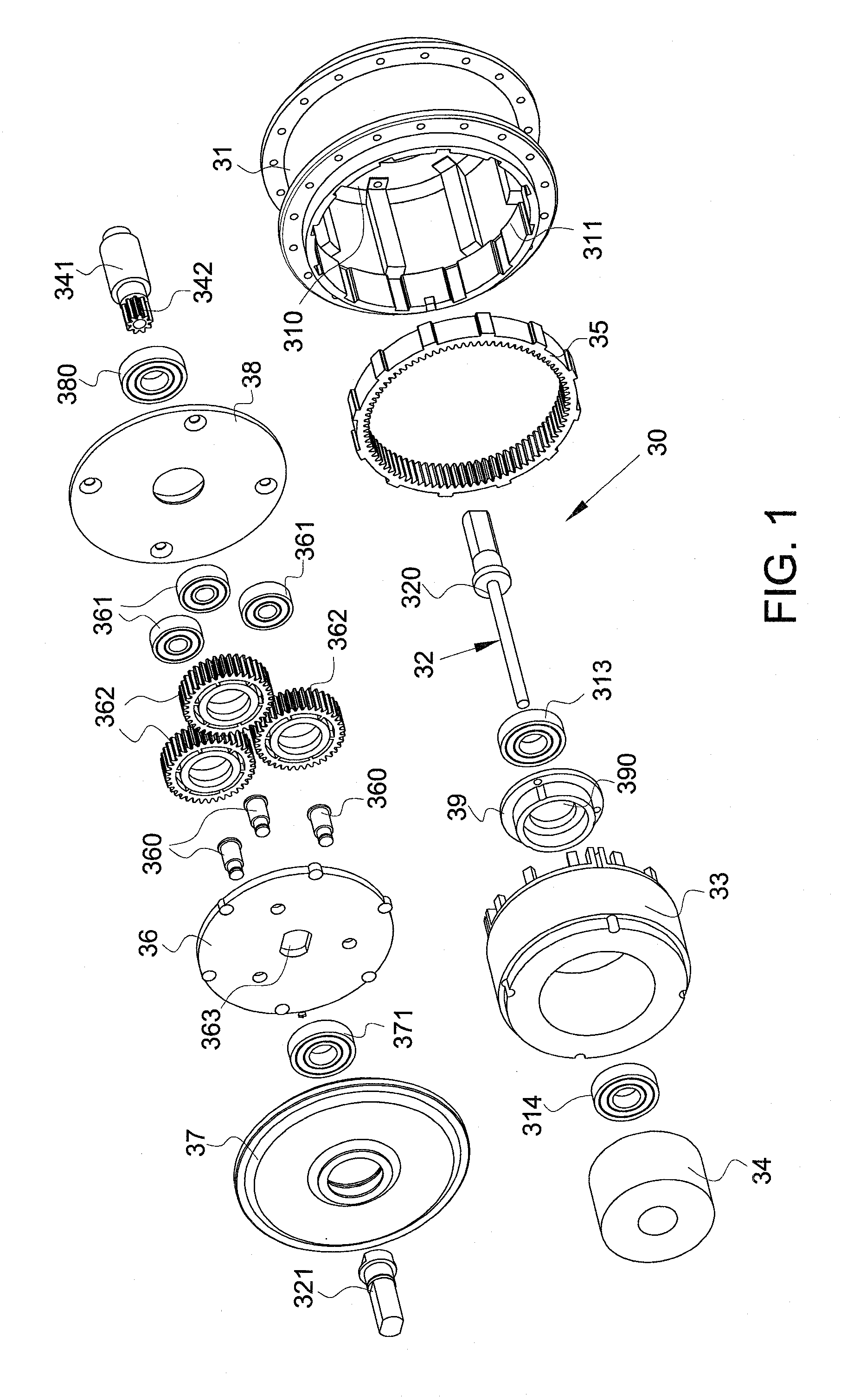
[0008]The first object of the present invention is to provide a hub motor for electric vehicles and the hub motor includes a rim, connecting members, a motor housing, a gear ring, a coil unit, a shaft, a tube, a magnet unit, a sun gear, a planet gear frame and multiple planet gears. The gear ring and the coil unit are fixed in the motor housing and two bearings are located between the shaft and the motor housing so that the motor housing is rotatable relative to the shaft. The tube has the magnet unit and the sun gear, and the planet gear frame is fixed to the shaft and the planet gears are connected to the planet gear frame. The planet gears are engaged with the gear ring and the sun gear. By this arrangement, the hub motor is simplified and easily assembled to the electric vehicles.
[0010]The third object of the present invention is to provide a hub motor which has its own power supply and has an integral body so as to easily assemble to different electric vehicles. The wires of the hub motor do not need to extend along the whole frame of the vehicles. The connecting members of the rim fix the motor housing, the battery and the control device. The battery provides electric power to the hub motor and the control device receives a wireless command signal and generates a control signal to control the battery to provide power to the hub motor.

Problems solved by technology

There are different types of driving mechanisms for electric vehicles and the hub motors are developed to improve the shortcomings of the conventional driving mechanism which require long transmission system and are not suitable for electric wheeled chairs.
Most of the conventional hub motors involve complicated structure so as to have required output work, and the complicated structure includes large number of parts which are costly and take a lot of time for assembly, and maintenance cost is significant.
The battery is usually bulky and heavy so that the battery has to be connected to the strong portion of the frame such as the seat tube or the carriage rack.
Therefore, the wires have to extend a long distance along the frame and this obviously cannot achieve the aesthetic purpose and requires a significant time to position the wires.
In addition, the hole in the shaft may weaken the structure of the shaft.
Some wheels are equipped with power generating members which operate only when the wheels rotate and are not designed for directly providing electric power to the rotation of the wheels.
The conventional hub motors are complicated and do not have battery directly connected to the rim.

Method used


Image

  • Hub motor for electric vehicles
  • Hub motor for electric vehicles
  • Hub motor for electric vehicles

Examples


Embodiment Construction

[0026]To achieve the first purpose of the present invention, referring to FIGS. 1-6, the hub motor 30 of the present invention is to be installed on a rim 10, the rim 10 has a tire 20 connected to an outer periphery thereof and at least one connecting member 11 is connected to an inside of the rim 10. The hub motor 30 of the present invention comprises a cylindrical motor housing 31 which is fixed to the at least one connecting member 11 and located at the center of the rim 10; a gear ring 35 and a coil unit 33 are fixed to an inside of the motor housing 31; a shaft 32 extends through the motor housing 31 and located on the central axis of the motor housing 31 and the center of the rim 10, and two ends of the shaft 32 are fixed to a vehicle frame 60 (referring to FIG. 9); a first bearing 313 and a second bearing 371 are located between the motor housing 31 and the shaft 32 so that the motor housing 31 is rotatable about the shaft 32.

[0027]The shaft 32 extends through a tube 341 and ...


PUM


Abstract

A hub motor for electric vehicles and includes a rim, connecting members, a motor housing, a gear ring, a coil unit, a shaft, a tube, a magnet unit, a sun gear, a planet gear frame and multiple planet gears. The gear ring and the coil unit are fixed in the motor housing and two bearings are located between the shaft and the motor housing so that the motor housing is rotatable relative to the shaft. The tube has the magnet unit and the sun gear, and the planet gear frame is fixed to the shaft and the planet gears are connected to the planet gear frame. The planet gears are engaged with the gear ring and the sun gear. By this arrangement, the hub motor is simplified and easily assembled to the electric vehicles.

Description

FIELD OF THE INVENTION[0001]The present invention relates to a hub motor for electric vehicles, and more particularly, to a hub motor wherein the coil unit and the magnet unit are rotated relative to each other about the shaft so as to obtain a simple structured and high efficiency hub motor.BACKGROUND OF THE INVENTION[0002]There are different types of driving mechanisms for electric vehicles and the hub motors are developed to improve the shortcomings of the conventional driving mechanism which require long transmission system and are not suitable for electric wheeled chairs. The conventional hub motors are disclosed in U.S. Pat. Nos. 3,897,843, 4,346,777, 4,913,258, 7,719,412 and 6,974,399, and applicant owned U.S. Pat. No. 6,974,399. All of the disclosures relate to the use of electric motor directly driving the wheels.[0003]Most of the conventional hub motors involve complicated structure so as to have required output work, and the complicated structure includes large number of ...

Claims


Application Information

Patent Timeline
IPC IPC(8): F16H48/06B60K7/00
CPCB60K1/04B60K7/0007B60K2001/045B60K2007/0038Y10T477/30B60Y2200/84B62M6/65F16H57/08B60K2007/0092
Inventor LO, CHIU-HSIANG
Owner LO CHIU HSIANG
Learn More