
Self-cleaning air filter

a self-cleaning, air filter technology, applied in the direction of filtration separation, separation process, transportation and packaging, etc., can solve the problem of premature interruption of the cleaning action provided by the compressed air puls

Active Publication Date: 2012-03-29
MARADYNE CORP
View PDF7 Cites 36 Cited by
  • Summary
  • Abstract
  • Description
  • Claims
  • Application Information

AI Technical Summary

Benefits of technology

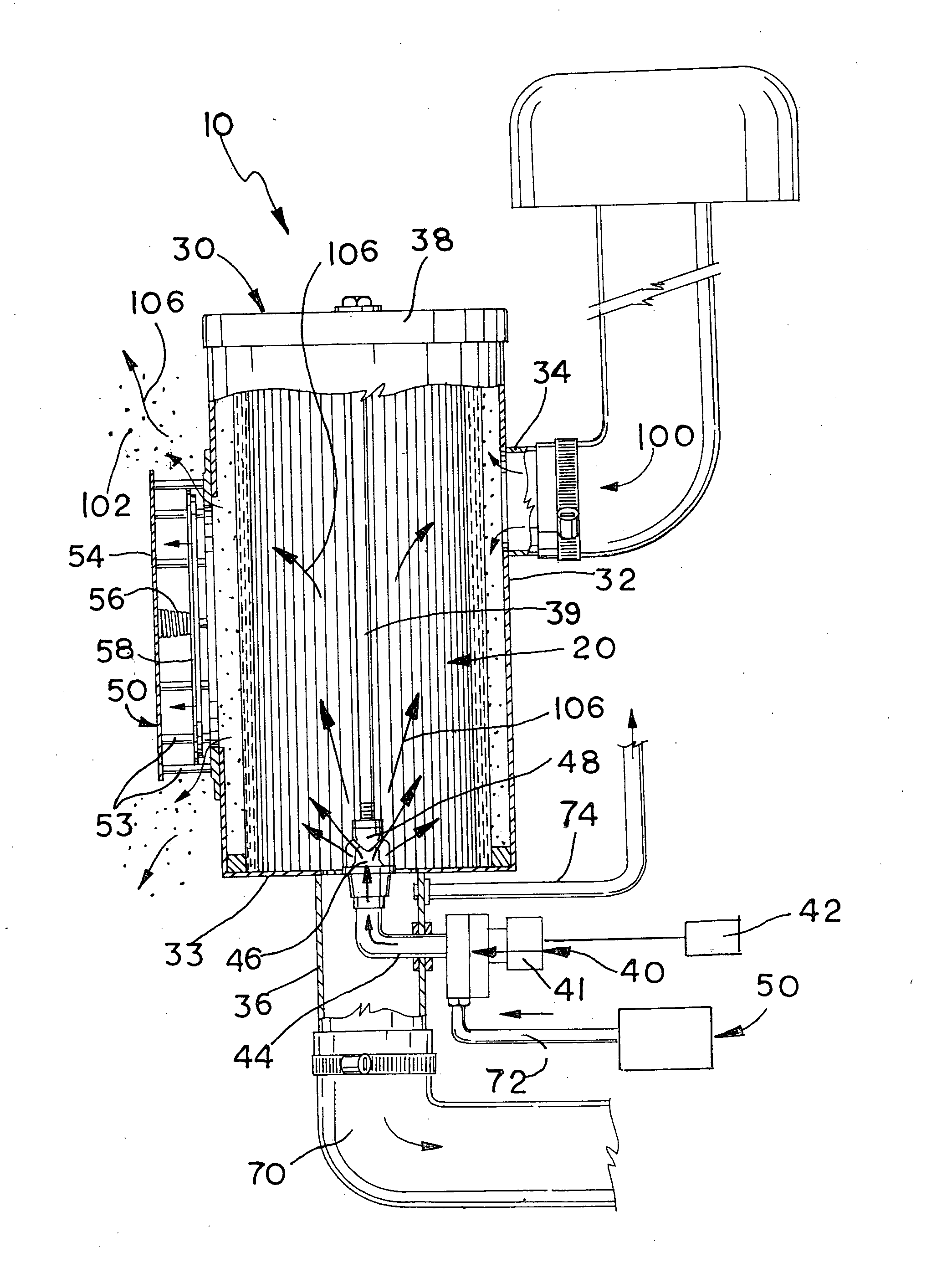
[0006]The present invention provides a reverse pulse self-cleaning air filter for use in small scale, small filter volume applications, such as for vehicles and other motorized equipment. In one embodiment of this invention, the self-cleaning air filter includes a filter casing, a filter element housed within a filter casing, an electronically controlled pulse valve that releases the compressed air pulse, and a pulse pressure relief vent. The pulse pressure vent enables the air filter's use of the reverse pulse self-cleaning. During the cleaning cycle, the pulse pressure vent opens to vent the compressed air pulse to the atmosphere thereby maintaining the positive pressure differential between the inside and outside of the filter element, which sustains the cleaning action for the duration of the pulse. The pulse pressure vent compensates for the filter casing's small confined volume where the compressed air pulse is normally dissipated in large industrial systems by venting the compressed air pulse from the casing. Without the pulse pressure vent venting the compressed air pulse to the atmosphere, the pressure differential between the inside and outside of the filter element would quickly equalize within the confined space of the filter casing, thereby prematurely interrupting the cleaning action provided by the compressed air pulse.

Problems solved by technology

Without the pulse pressure vent venting the compressed air pulse to the atmosphere, the pressure differential between the inside and outside of the filter element would quickly equalize within the confined space of the filter casing, thereby prematurely interrupting the cleaning action provided by the compressed air pulse.

Method used


Image

  • Self-cleaning air filter
  • Self-cleaning air filter
  • Self-cleaning air filter

Examples


Embodiment Construction

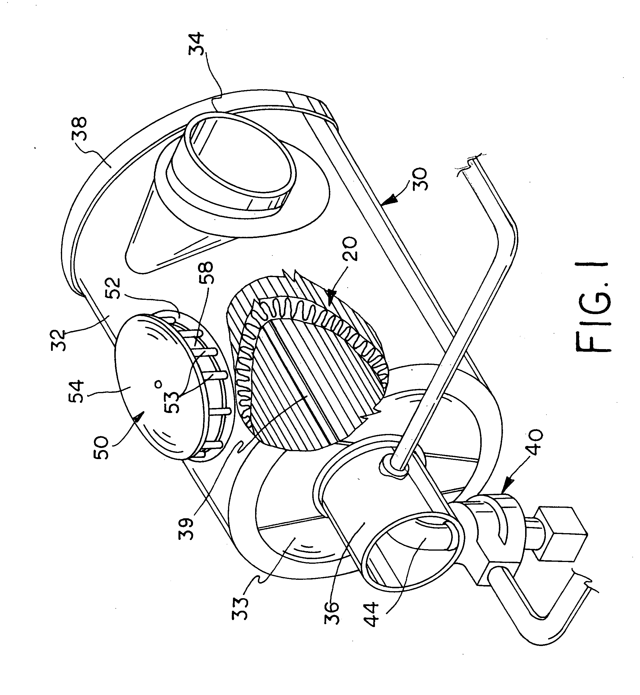
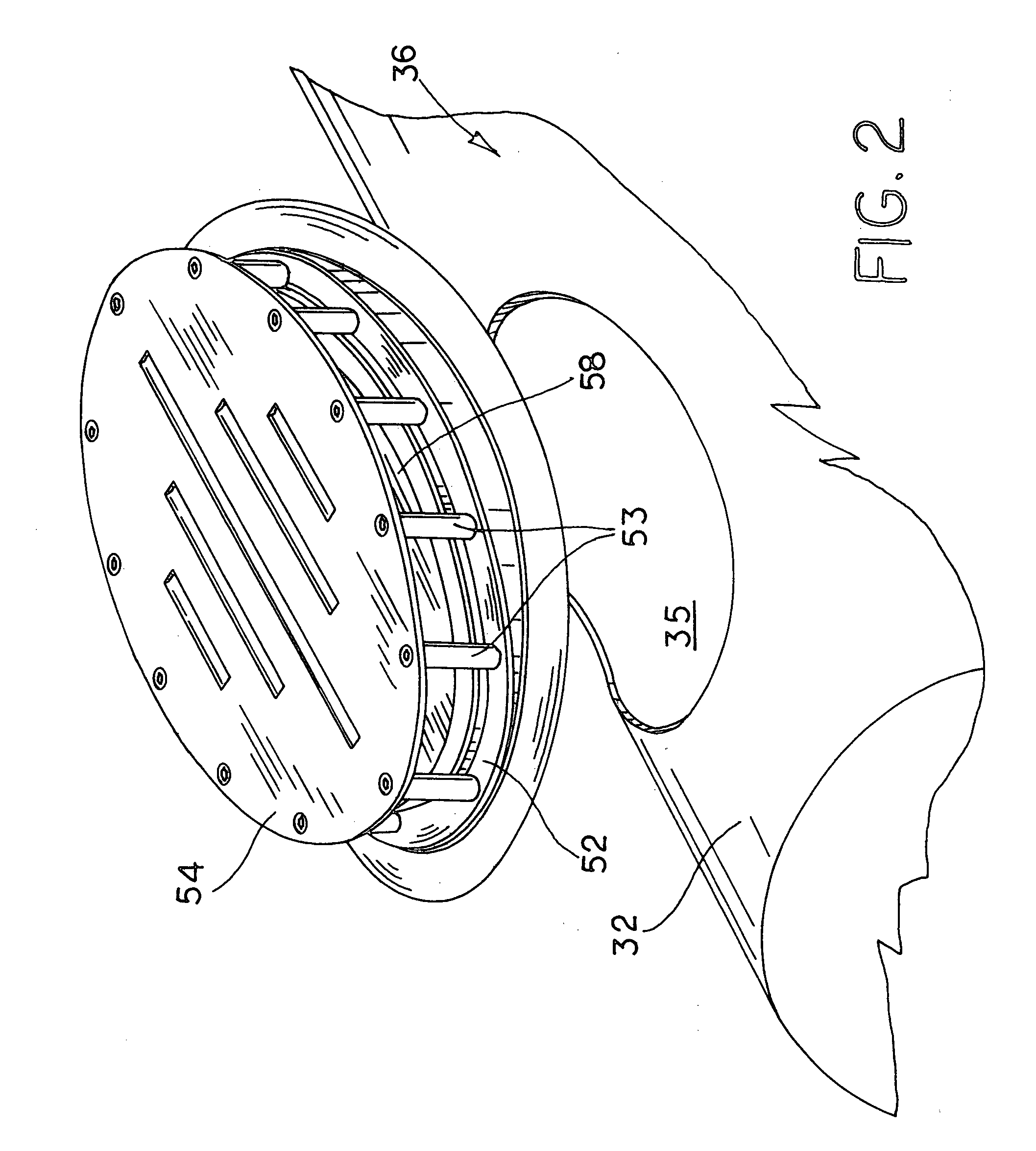
[0018]FIGS. 1-9 illustrate an embodiment of the self-cleaning air filter of this invention, which is designated generally as reference numeral 10. As shown, air filter 10 includes a tubular filter element 12 disposed within a cylindrical filter casing 20. Filter element 12 is of conventional design and function having a tubular sidewall of pleated filter material, which collects dust and debris as air passes through. Filter element 12 is constructed of synthetic fibers rather than conventional paper. Filter element 12 is axially centered within filter casing 20. The tubular sidewall of filter element 12 is inset from the casing sidewalls defining an open space 13 around the outside of the filter element. The tubular sidewall also defines an open interior space 15 within filter element 12. Filter casing 20 has an open end enclosed by a removable lid 28. Lid 28 allows filter element 12 to be replaced as desired. Lid 28 is secured to casing 20 by connecting rod 29, which extends axiall...


PUM

PropertyMeasurementUnit
Pressureaaaaaaaaaa
Internal pressureaaaaaaaaaa

Abstract

The self-cleaning air filter uses reverse pulse self-cleaning for small scale, small volume air filtration applications, such as vehicles and motorized equipment. The self-cleaning air filter includes a filter casing, a filter element housed within a filter casing, an electronically controlled pulse valve that releases the compressed air pulse, and a pulse pressure relief vent. During the cleaning cycle, the pulse pressure vent opens to vent the compressed air pulse to the atmosphere thereby maintaining the positive pressure differential between the inside and outside of the filter element, which sustains the cleaning action for the duration of the compressed air pulse.

Description

[0001]This invention relates to a self-cleaning air filter, and in particular a self-cleaning air filter for vehicles and motorized equipment.BACKGROUND OF THE INVENTION[0002]Operating in dusty environments has long been a problem for equipment and vehicles. The respiration of dusty and contaminated air greatly hinders performance and can damage the vehicle or equipment's engines. Even though vehicles and equipment have filter elements that filter the inlet air flow, in extremely dusty environments, these filter elements quickly become caked with dust and debris, which retards and stops the air flow through the filter element to the engine. Consequently, these filter elements must be frequently cleaned to remove the “dusty cake” formed on the outside of filter elements or the entire filter element must be replaced to ensure the proper operation of the equipment and vehicles. In extremely dusty environments, the demand of constantly cleaning and / or replacing filter elements comes at ...

Claims


Application Information

Patent Timeline
IPC IPC(8): B01D29/66
CPCB01D46/0068B01D46/4272B01D46/2403B01D46/71
Inventor TROXELL, RONALD C.TROXELL, JASON D.
Owner MARADYNE CORP
Learn More