
Golf swing wrist condition training device

a training device and golf swing technology, applied in golf, golf accessories, sport apparatus, etc., can solve the problems of unnecessary and tremendously destructive flattening of the right, loss of distance and direction of the golf ball, and virtually insurmountable timing challenges

Active Publication Date: 2012-03-22
KYRON
View PDF8 Cites 8 Cited by
  • Summary
  • Abstract
  • Description
  • Claims
  • Application Information

AI Technical Summary

Benefits of technology

"The present invention is a golf swing training device that helps maintain a desirable bent wrist condition during the entire golf swing, including the impact with the golf ball. The device allows the user to start the swing with the right wrist in its natural, flattened condition and then bend it back naturally to represent different amounts of bend for shorter and longer strokes. Once the wrist reaches its full bend at the top of the backswing, the device effectively maintains it throughout the downswing and finish of the swing. This invention helps improve the golfer's swing consistency and accuracy."

Problems solved by technology

One of the biggest, if not the biggest problem, golfers battle in trying to develop and maintain an effective golf swing is the unnecessary and tremendously destructive flattening of the right wrist (in the case of a right-handed golfer) prior to or during the impact of the club face on the golf ball and separation of the ball therefrom.
The stifling effects of a flattening right wrist of a right handed golfer during the downswing includes the loss of control of all three of the aforementioned components of the golf club, thereby resulting in a loss of distance and direction of the golf ball.
This, however, gives rise to a virtually insurmountable timing challenge that golfers struggle with and thus prevents consistency in the golf swing.
However, these currently known products possess certain deficiencies which detract from their overall utility.
However, the full amount of wrist bend in the right wrist is typically not achieved by a player until the top of the backswing has been reached.

Method used


Image

  • Golf swing wrist condition training device
  • Golf swing wrist condition training device
  • Golf swing wrist condition training device

Examples


first embodiment

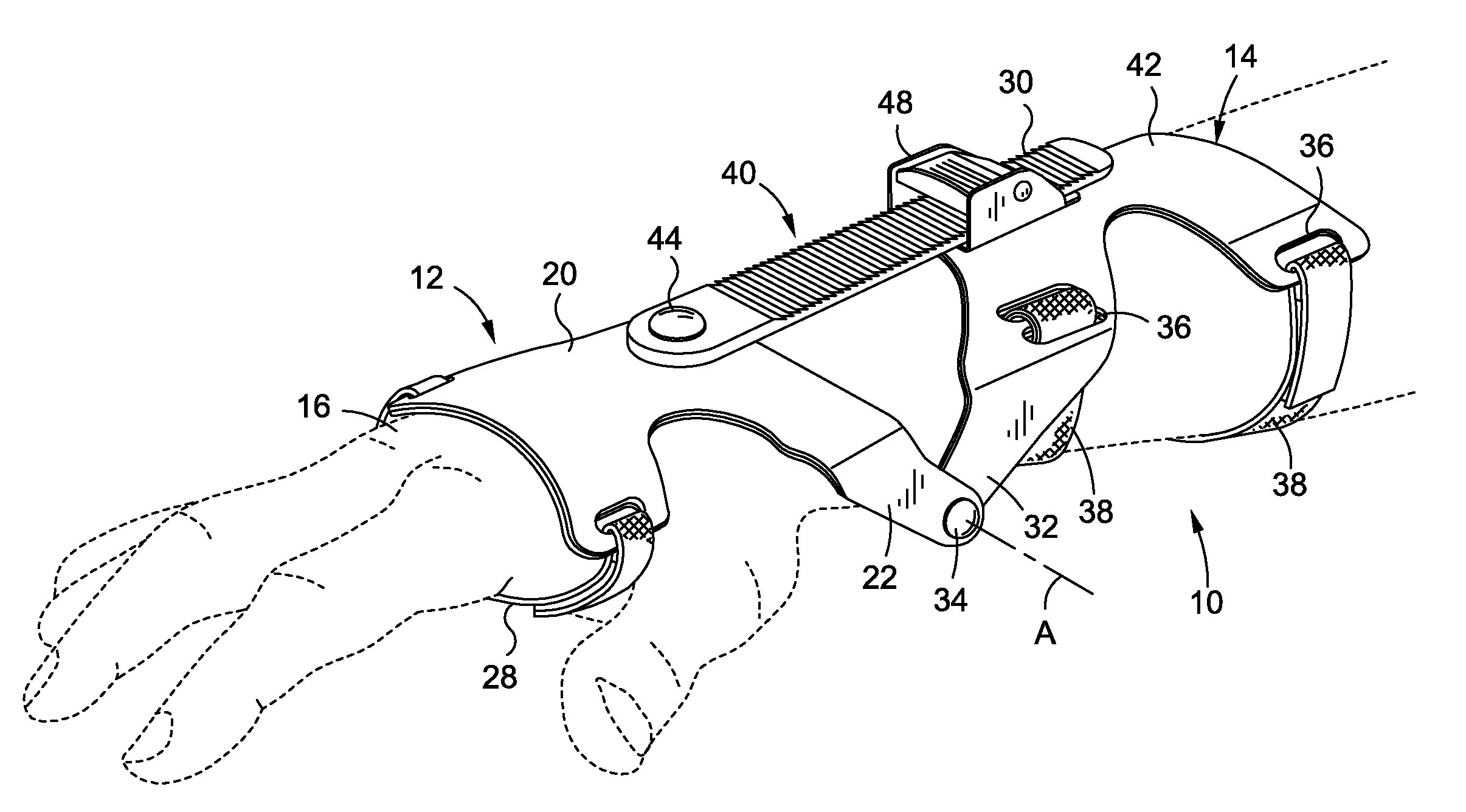
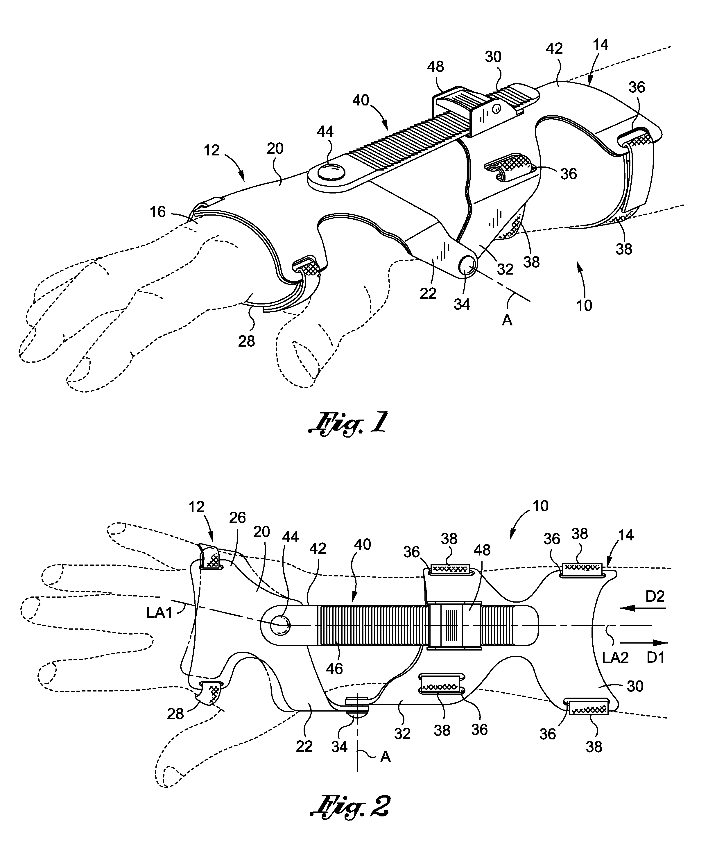
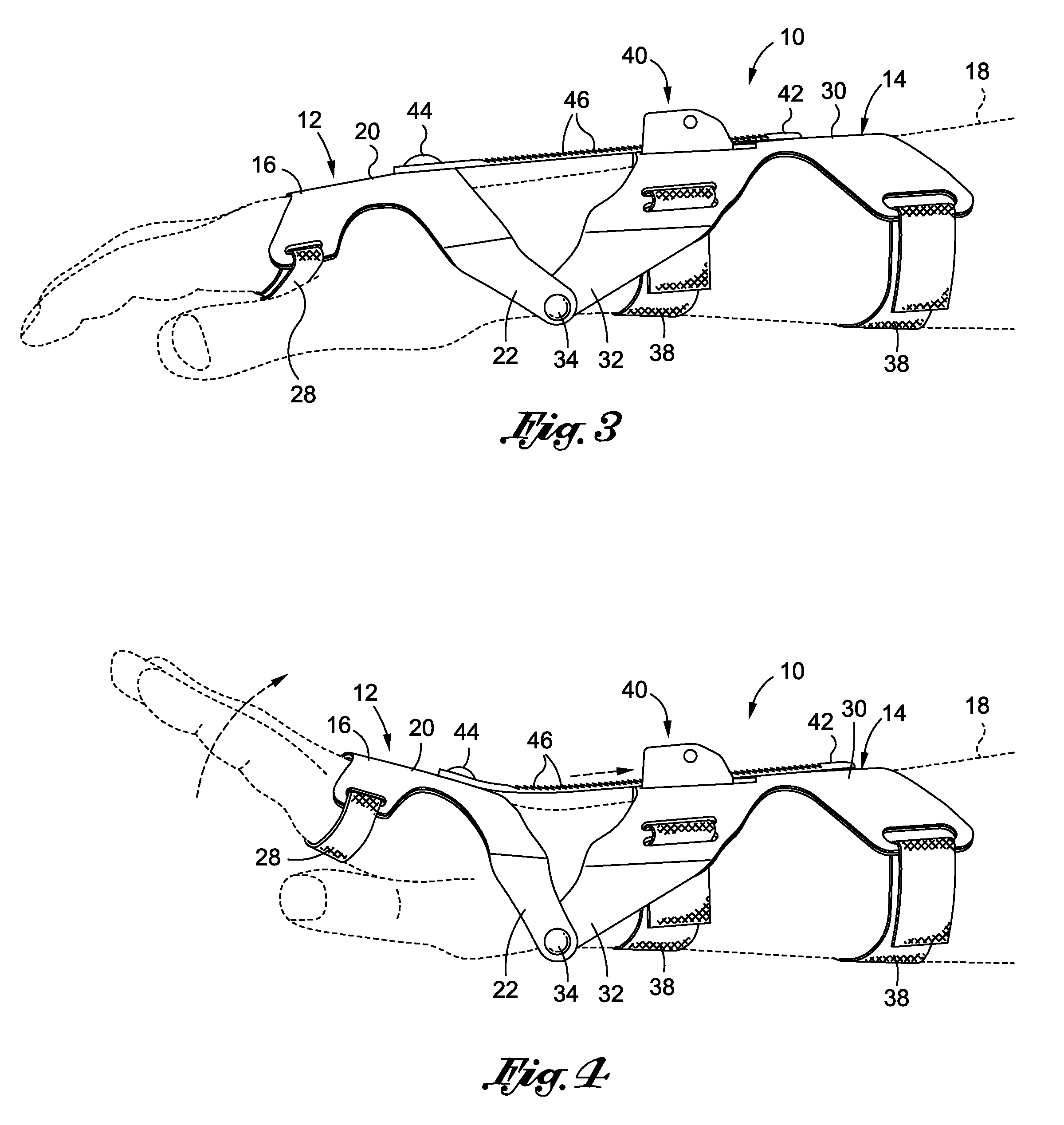
[0029]The training device 10 of the first embodiment comprises a hand plate 12 and a forearm plate 14 which are pivotally connected to each other. As will be discussed in more detail below, the pivotal connection of the hand and forearm plates 12, 14 to each other is adapted to facilitate the selective pivotal movement of the hand plate 12 relative to the forearm plate 14 about an axis A which is shown and labeled in FIGS. 1 and 2. As best seen in FIGS. 3 and 4, the hand plate 12 of the training device 10 is configured to be positionable upon the posterior surface of the right hand 16 of the user, the posterior surface of the right hand 16 being that surface which is opposite the anterior or palmer surface of the right hand 16. The forearm plate 14 is itself adapted to be positionable upon the posterior surface of the right forearm 18 of the user. In this regard, both the hand plate 12 and forearm plate 14, when operatively positioned upon the right arm of the user, are each adapted...

second embodiment

[0045]In the training device 100 of the second embodiment, the aforementioned ratchet mechanism 134 effectively functions as a wrist condition retention device. When viewed from the perspective shown in FIGS. 5, 7, 8 and 9, the ratchet mechanism 134 allows for the pivotal or rotatable movement of the hand plate 112 relative to the forearm plate 114 about the axis A in a clockwise direction, but normally prevents the pivotal or rotatable movement of the hand plate 112 relative to the forearm plate 114 about the axis A in a counter-clockwise direction. However, the ratchet mechanism 134 is outfitted with a release switch which, when selectively actuated by the user, allows for the pivotal or rotatable movement of the hand plate 112 relative to the forearm plate about the axis A in a counter-clockwise direction. Those of ordinary skill in the art will recognize that the structural and functional attributes of the ratchet mechanism 134 minor, in large measure, the structural and functio...

third embodiment

[0052]The training device 200 of the third embodiment further comprises a wrist condition retention assembly 240 which is attached to and effectively interconnects the hand and forearm plates 212, 214 to each other. The retention assembly 240 comprises an elongate ratchet strap 242, one end of which is attached to the hand plate 212. More particularly, as best seen in FIGS. 12 and 14, the attachment of one end of the ratchet strap 242 to the hand plate 212 is facilitated by an attachment knob 244. However, those of ordinary skill in the art will recognize that mechanical structures other than for the attachment knob 244 may be used to facilitate the attachment of the ratchet strap 242 to the hand plate 212 without departing from the spirit and scope of the present invention. As is most apparent from FIGS. 11, 12 and 15, the ratchet strap 242 is formed to include a multiplicity of serrations or teeth 246 along the majority of the length thereof.

[0053]In addition to the ratchet strap ...


PUM


Abstract

In accordance with the present invention, there is provided a golf swing training device which is uniquely configured to maintain a desirable bent wrist condition through the entirety of the downswing (including golf ball impact) and follow-though or finish of the golf swing. The training device allows the wearer to start the golf swing with the right wrist in its natural, generally flattened condition at address. Once the backswing of the golf stroke is initiated, the training device allows the wearer to bend the right wrist back naturally, and at different amounts so as to represent the different amounts of right wrist bend a golfer may employ for shorter and longer strokes. Once the right wrist has achieved its full amount of bend at the time of the downswing, the training device effectively maintains such bend throughout the entirety of the downswing and follow-through or finish of, the golf swing.

Description

CROSS-REFERENCE TO RELATED APPLICATIONS[0001]The present application claims priority to U.S. Provisional Patent Application Ser. No. 61 / 384,614 entitled GOLF SWING WRIST CONDITION TRAINING DEVICE filed Sep. 20, 2011, the disclosure of which is incorporated herein by reference.STATEMENT RE: FEDERALLY SPONSORED RESEARCH / DEVELOPMENT[0002]Not ApplicableBACKGROUND OF THE INVENTION[0003]1. Technical Field of the Invention[0004]The present invention relates generally to the game of golf and, more particularly, to a golf swing training device which is uniquely configured to maintain a desirable bent wrist condition through the entirety of the downswing (including golf ball impact) and follow-though or finish of the golf swing.[0005]2. Description of the Related Art[0006]In the game of golf, in order to control the golf ball, one must control the instrument (i.e., the golf club). The golf club consists of three primary components, which are the club head, the club shaft, and the club face. O...

Claims


Application Information

Patent Timeline
Patent Type & Authority Applications(United States)
IPC IPC(8): A63B69/36
CPCA63B69/0059A63B69/3608A63B2209/10A63B2209/023A63B2071/0633
Inventor SHEW, ROBERT SCOTTSCHOEN, CARY R.
Owner KYRON
Learn More