Centrifugal blower

a centrifugal blower and centrifugal technology, which is applied in the direction of machines/engines, stators, liquid fuel engines, etc., can solve the problems of insufficient noise reduction effect, interference of backflow, and inability to prevent backflow entry, so as to reduce the noise level

Active Publication Date: 2012-03-08
NIPPON SOKEN +1
View PDF10 Cites 9 Cited by
  • Summary
  • Abstract
  • Description
  • Claims
  • Application Information

AI Technical Summary

Benefits of technology

[0010]The present invention was made in consideration of the above problem and provides a centrifugal blower provided with a scroll casing for automobile air-conditioning use which is effective for reducing the noise level.
[0012]Due to this, it is possible to change the shape of the chamber bottom part so as to improve the flow between blades and eddy formation and guide backflow well to the chamber bottom part so as to prevent the entry of an air flow between blades causing noise. Further, backflow is prevented and the formation of an eddy at the chamber bottom part is reduced, so the effect is obtained of reduction of the noise level and improvement of the fan efficiency.
[0018]The backflow prevention rib 3 is set at the outlet side, so it is possible to prevent in advance any flow entering between the blades and thereby reduce the noise and increase the fan efficiency.
[0019]An aspect of the invention according to claim 7 is the aspect of the invention according to claim 6 wherein the angle formed by the maximum width of the backflow prevention rib with respect to the circumferential direction is a range of angle of 5° to 25°. Due to this, it is possible to suppress the backflow which often occurs in a range of an angle φ of 5° to 25°. This is much more effective for reduction of the noise level and increasing the efficiency of the fan.
[0020]An aspect of the invention according to claim 8 is the aspect of the invention according to claim 6 wherein at any angle of the angle formed by the circumferential direction, a width W1 of a case top surface of the scroll chamber is smaller than a width W2 of a case bottom surface of the chamber bottom part. Due to this, even when backflow easily occurs due to the width W1 of the case top surface, it is possible to prevent disturbance in the flow.
[0022]Due to this, it is possible to prevent the air flow discharged from the multi-blade fan in the scroll chamber from striking the wall surfaces of the casing, striking the top of the fan wheel in the axial direction, or entering between the blades and possible to remarkably improve the noise level and the fan efficiency in the entire region of the range of use of the blower.

Problems solved by technology

For this reason, a sufficient noise reduction effect could not be obtained.
In this case, in the backflow phenomenon in which part of the flow inside the casing enters between the blades, it was not possible to prevent entry of the backflow between the blades in advance.
That is, backflow ends up entering inside the blades once, so the backflow interferes with the sucked in flow and the air flow between the blades is greatly disturbed.
Therefore, worse noise and a lower flow rate (lower efficiency) are invited.
Further, due to the provision of the plate 3′ set from the blade inlet side, even when backflow is not formed, suction resistance is formed and the overall flow rate is lowered to thereby cause a drop in efficiency.

Method used


Image

  • Centrifugal blower
  • Centrifugal blower
  • Centrifugal blower

Examples


first embodiment

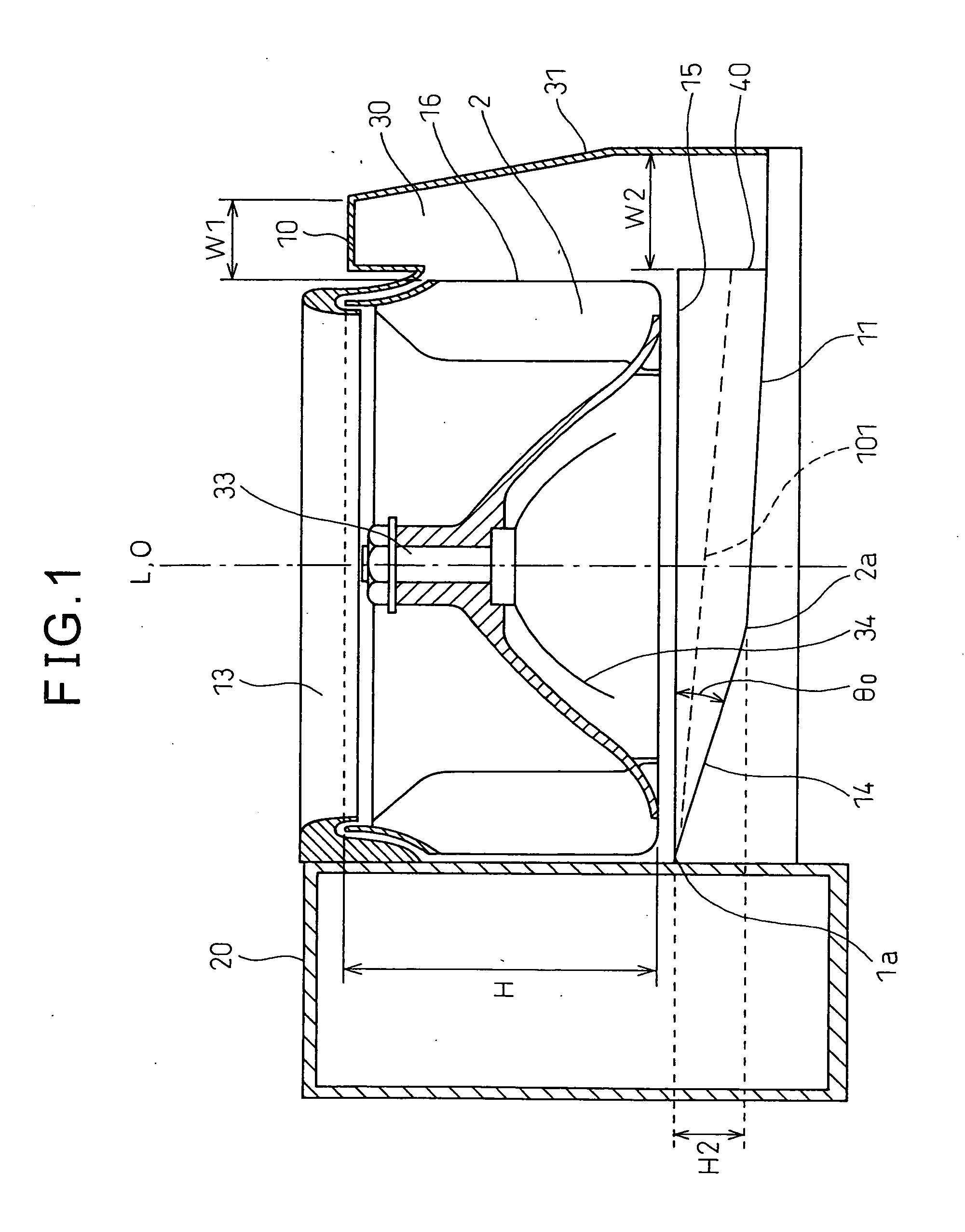
[0055]FIG. 1 is a cross-sectional view of a centrifugal blower in an embodiment of the present invention.

[0056]The centrifugal blower is provided with a multi-blade fan 16 which has a large number of blades 2, a motor 34 to which this multi-blade fan 16 is attached, and a casing 31 which houses the multi-blade fan 16 inside of the casing 31 and which has a scroll chamber 30 formed in a spiral shape at an outer circumference side of the multi-blade fan. The multi-blade fan referred to here is also called a “sirocco fan”. The casing 31 having the scroll chamber 30 is called a “scroll casing”.

[0057]The casing 31 has an air inlet 13 at the surface of one side of the multi-blade fan 16 in the axial direction. If the motor 34 turns, the multi-blade fan 16 sucks in air from the air inlet 13 to the center part of the multi-blade fan 16. At the centrifugal blower, air is sucked into the center part of the multi-blade fan, then is given kinetic energy (dynamic pressure) by this multi-blade fa...

second embodiment

[0075]FIG. 10 is a cross-sectional view of a centrifugal blower in another embodiment of the present invention. FIG. 11 is a schematic view explaining a backflow prevention rib. The other embodiment of the present invention is explained with reference to the case of application to a centrifugal blower provided with a scroll casing for automobile air-conditioning use, but is not limited to automobile air-conditioning use.

[0076]Below, referring to FIG. 10, another embodiment of the present invention will be explained. The centrifugal blower is provided with a multi-blade fan 16 having a large number of blades 2, a motor 34 to which this multi-blade fan 16 is attached, and a casing 31 which houses the multi-blade fan 16 inside of the casing 31 and has a scroll chamber 30 which is formed in a spiral shape at the outer circumference side of the multi-blade fan.

[0077]The casing 31 has an air inlet 13 at one surface of the multi-blade fan 16 in the axial direction. If the motor 34 rotates,...

third embodiment

[0092]Next, another embodiment of the present invention will be explained. FIG. 17 is a cross-sectional view of a centrifugal blower in the other embodiment of the present invention. FIG. 18 shows an example of the shape of the backflow prevention rib 3 showing the relationship between the angle φ from the spiral start part 1a to the circumferential direction and the maximum width h2 in the other embodiment of the present invention. FIG. 19 is a plan cross-sectional view in the other embodiment of the present invention.

[0093]In the other embodiment of the present invention, as shown in FIGS. 17 and 18, the backflow prevention rib 3 is shaped set in the scroll chamber 30 at the top end of the fan outlet in a range from 45° (−45°) at one side in the circumferential direction to 45° (+45°) at the other side in the circumferential direction from the spiral start part 1a as the starting point (0°). Further, the maximum width h2 of the backflow prevention rib 3, measured downward in the a...


PUM


Abstract

A centrifugal blower provided with a spiral shaped scroll chamber where a bottom part of the scroll chamber gradually expands downward in the axial direction of the fan well along with expansion of the spiral and where a flow area gradually expands toward an air outlet from a spiral start part of the casing, the centrifugal blower having an initial slant angle θ0 at the spiral start part of the bottom part of the scroll chamber of a range of angle of 5.2° to 27.5° or setting a backflow prevention rib at the fan outlet.

Description

TECHNICAL FIELD [0001]The present invention relates to a centrifugal blower provided with a scroll casing for automobile air-conditioning use.BACKGROUND ART [0002]A centrifugal blower used in an air-conditioning system for automobile use is, for example, disclosed in Japanese Unexamined Patent Publication No. 2004-360497. FIG. 24A is a cross-sectional view along the axial direction of a centrifugal blower of the prior art disclosed in Japanese Unexamined Patent Publication No. 2004-360497, FIG. 24B is a front view, and FIG. 24C is a plan cross-sectional view.[0003]Such a conventional centrifugal blower is provided with a multi-blade fan 16 having a large number of blades 2, a motor 34 to an output shaft 33 of which this multi-blade fan 16 is attached, and a casing 31 housing the multi-blade fan 16 inside it and having a scroll chamber 30 formed in a spiral shape at an outer circumferential side of the multi-blade fan. The scroll chamber 30 is formed in a spiral shape which starts fr...

Claims


Application Information

Patent Timeline
IPC IPC(8): F01D25/24
CPCF04D17/16F04D29/4226F04D29/4213F04D17/162F04D29/4233F04D17/10
Inventor MITSUISHI, YASUSHISAKAI, MASAHARUYASUDA, MASANORIIMAHIGASHI, SHOUICHIISHIGURO, SYUNSUKE
Owner NIPPON SOKEN
Why Eureka
Try Eureka