
Scaffold tray

a technology for scaffolds and trays, applied in the field of scaffolds, can solve the problems of reducing the number of movable parts that are vulnerable to wear and fracture, and achieve the effects of reducing the likelihood of wind disengaging the scaffolds, facilitating the necessary push-fit of the scaffolds, and reducing the cost associated

Inactive Publication Date: 2012-03-08
MOORE PHILIP
View PDF8 Cites 3 Cited by
  • Summary
  • Abstract
  • Description
  • Claims
  • Application Information

AI Technical Summary

Benefits of technology

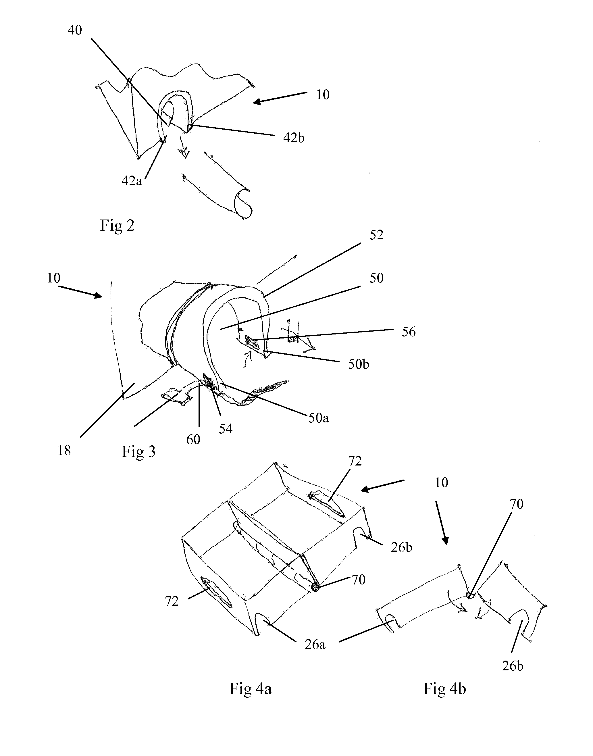
[0025]When the tray is in use, it will generally be positioned at a substantial height above ground level. It is therefore advantageous if the tray has means to resist any inadvertent disengagement, in use, of the tray from the, or each, pole. Such means reduce the likelihood of the wind disengaging the tray, or a person from knocking the tray and it disengaging.
[0027]In a preferred embodiment, the tray incorporates means to lock the underside of the tray, in use, to the pole. Such a locking means further reduces the likelihood of unintentional disengagement.
[0029]In one embodiment the tray folds, when not in use, for carrying. It is advantageous if the tray folds about its base. Preferably, the tray is provided with cut-outs or indentations in each of its lipped regions which face one another across the fold line of the tray so that, when the tray folds for carrying, the cut-outs or the indentations coincide to form a carrying handle. Such a carrying handle makes the tray easy to carry up scaffolding towers and also allow one to carry the tray in one hand. By folding about the base, the tray is solid when in use, but can be easily folded when not.

Problems solved by technology

Furthermore, the use of a yieldable material reduces the number of movable parts that are vulnerable to wear and fracture.

Method used


Image

  • Scaffold tray
  • Scaffold tray
  • Scaffold tray

Examples


Embodiment Construction

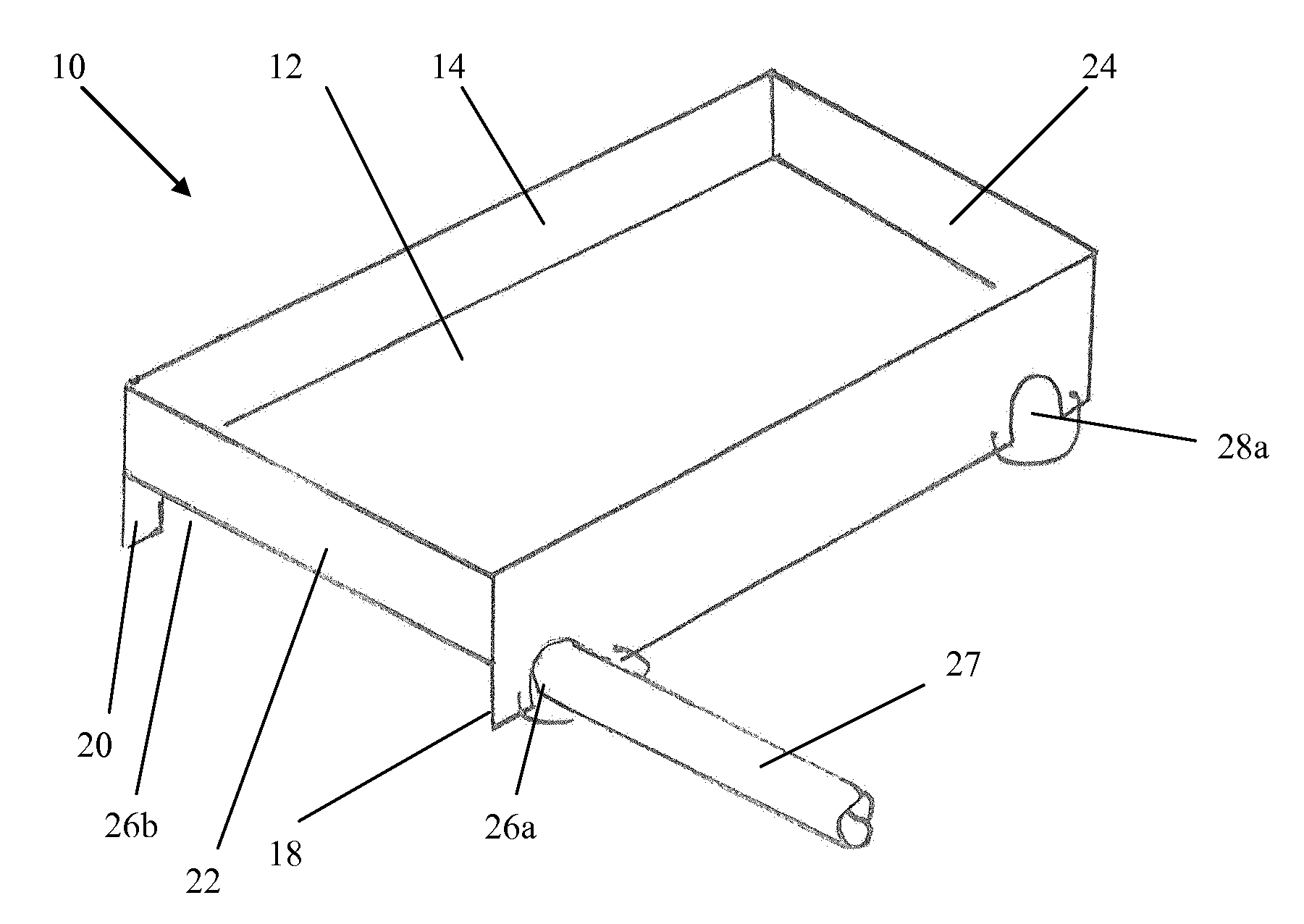
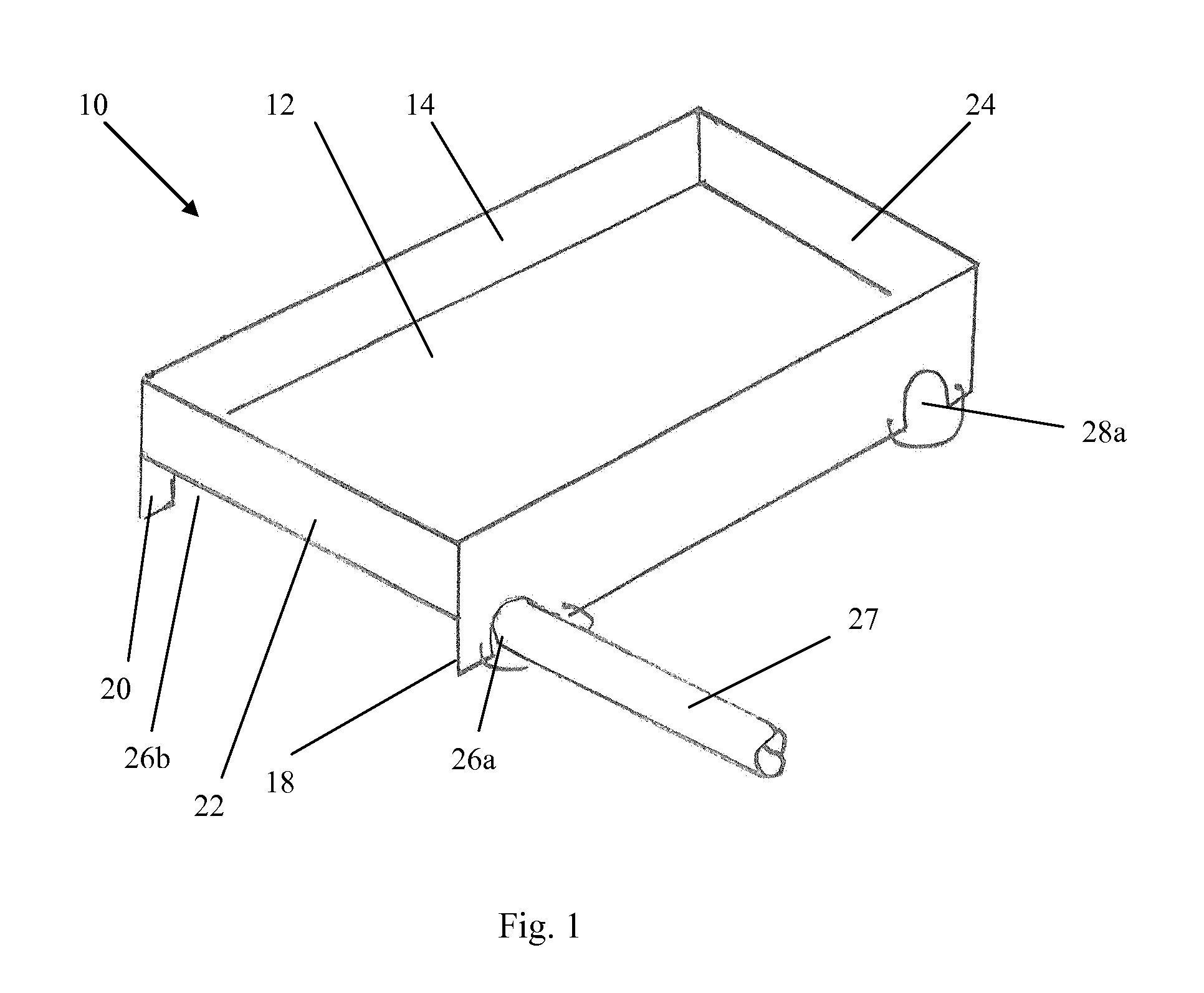
[0036]FIG. 1 shows a lipped tray 10, for use on scaffolding towers, comprising a base portion 12, having a generally rectangular profile. An upwardly extending lip 14 is provided around the perimeter of the base portion 12. Along the long sides of the base portion 12 are downwardly extending skirt portions 18 and 20.

[0037]In the region adjacent to each of the smaller sides 22 and 24 of the base portion 12, a first recessed arc 26a is cut at one end of the skirt portion 18, and a corresponding recessed arc 26b is cut into the skirt portion 20 in a position substantially the same distance from the end of the base 12. The diameter of the recessed arcs 26a and 26b is sufficient to receive a scaffolding pole 27. Corresponding arcs 28a and 28b (not shown) are provided adjacent to the side 24 of the base from 26a and 26b in the skirt portions 18 and 20.

[0038]When in use, the tray 10 is positioned to engage two substantially horizontally successive scaffolding poles, within the arcs 26a, 26...


PUM


Abstract

The present invention discloses a lipped tray, intended for use on scaffold towers and adapted to hold builders' tools in use. The tray incorporates on each of its two opposite side edge regions a means which, when the tray is in use, locates the tray between horizontally successive rails of the tower in a manner which also causes the tray to engage with one at least of those rails and be supported, in use, by each of them.

Description

FIELD OF THE INVENTION[0001]This invention relates to a scaffold tray adapted for holding tools and for use on a scaffold tower.BACKGROUND TO THE INVENTION[0002]When tradesmen work on scaffolding towers, they require a safe and secure surface on which to place their tools and materials. If a tool falls from a scaffold tower, it can cause a large amount of damage to an object or a person below. Therefore, tools need to be safely positioned while not in use, but also need to be readily available to the tradesman. Furthermore, when the tradesman has completed their work, the tray until needs to be removed from the scaffold tower before the scaffold tower is disassembled.[0003]Known to the applicant are the following published patent specifications;[0004]U.S. Pat. No. 3,020,972 A (Hockett)[0005]U.S. Pat. No. 4,979,710 A (Baldwin)[0006]These two documents relate to trays that fit onto conventional ladders. Both devices rely upon two hooks engaging a horizontal bar of the ladder, and the ...

Claims


Application Information

Patent Timeline
Patent Type & Authority Applications(United States)
IPC IPC(8): B65D1/34
CPCE04G7/28E04G5/00E04G5/003B65D1/34
Inventor MOORE, PHILIP
Owner MOORE PHILIP
Learn More