
Unmanned underwater vehicle and method for operating an unmanned underwater vehicle

a technology for underwater vehicles and underwater vehicles, applied in waterborne vessels, underwater equipment, special-purpose vessels, etc., to achieve accurate positioning and improve navigation of underwater vehicles

Inactive Publication Date: 2012-03-08
ATLAS ELEKTRONIC GMBH
View PDF6 Cites 17 Cited by
  • Summary
  • Abstract
  • Description
  • Claims
  • Application Information

AI Technical Summary

Benefits of technology

[0013]The underwater vehicle advantageously has an operating mode selection means which can be used to set either the autonomous operating mode or the remotely controlled operating mode as required. The underwater vehicle can therefore be operated as an AUV or ROV depending on the need of a mission to be specifically performed. In this manner, for example when investigating a wall under water, the underwater vehicle can quickly cover that working area of the wall which is to be investigated, for example during an interval, with the autonomous operating mode. If damage is detected, the underwater vehicle is changed over to the remotely controlled operating mode. In the remotely controlled operating mode, an operator can locally investigate the location in question and can repair it, possibly with the aid of the underwater vehicle.
[0022]The manoeuvring drive is advantageously provided in the region of the bow of the underwater vehicle and thus enables improved navigation of the underwater vehicle, if appropriate in a manner suitably matched to the main drive. The lateral linear drive is advantageously provided as a lateral linear drive on both sides of the hull. Alternatively or additionally, lifting drives may be provided as manoeuvring drives.

Problems solved by technology

As a result, underwater tasks with a need for large-scale reconnaissance and, at the same time, selective, that is to say locally limited, investigations under real-time conditions can be carried out by an individual unmanned underwater vehicle.

Method used


Image

  • Unmanned underwater vehicle and method for operating an unmanned underwater vehicle
  • Unmanned underwater vehicle and method for operating an unmanned underwater vehicle
  • Unmanned underwater vehicle and method for operating an unmanned underwater vehicle

Examples


Embodiment Construction

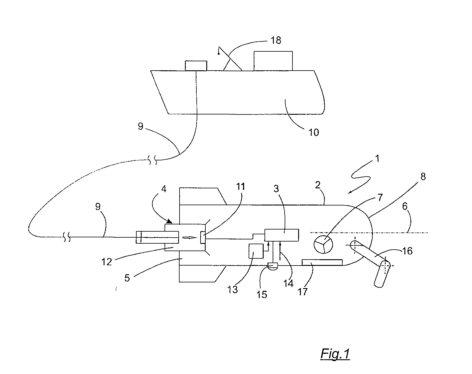
[0029]FIG. 1 shows an unmanned underwater vehicle 1 with a pressure-resistant hull 2. Different operating devices of the underwater vehicle 1 are arranged in or on the hull 2, for example power supply, communication, navigation and drive devices. The operating devices which are not illustrated in any more detail are controlled by a control device 3 of the underwater vehicle according to predefinable control commands. The underwater vehicle 1 also comprises suitable sensors, for example sonar sensors, the measurement results of which are used by the control device 3 to control the operating devices, for example for the purpose of navigation.

[0030]The unmanned underwater vehicle 1 has a main drive 4 in the region of its stern 5, which drive acts in a longitudinal direction 6 of the underwater vehicle 1. In addition to the main drive 4, the underwater vehicle 1 has a manoeuvring drive 7 which acts in a direction which differs from the longitudinal direction 6 and enables accurate posit...


PUM


Abstract

The invention relates to an unmanned underwater vehicle (1) which can be controlled according to predefinable control information by means of a control device (3). The invention also relates to a method for operating an unmanned underwater vehicle (1). To reduce the outlay for investigations of underwater areas using unmanned underwater vehicles, the invention provides for the underwater vehicle (1) to be able to be controlled either in an autonomous operating mode or in a remotely controlled operating mode, predetermined internal control information from a memory element (13) being able to be predefined to the control device (3) in the autonomous operating mode and external control information being able to be predefined to the control device (3) via a communication device (11) of the underwater vehicle (1) in the remotely controlled operating mode.

Description

CROSS-REFERENCE TO RELATED APPLICATION[0001]The present application claims the priority of German Patent Application No. 10 2010 035 899.1, filed Aug. 31, 2010, the subject matter of which, in its entirety, is incorporated herein by reference.BACKGROUND OF THE INVENTION[0002]The invention relates to an unmanned underwater vehicle which can be controlled according to predefinable control information by means of a control device. The invention also relates to a method for operating such an unmanned underwater vehicle.[0003]Unmanned underwater vehicles open up a multiplicity of possibilities for different underwater work. In contrast to manned underwater vehicles, unmanned systems can reach greater working depths and can operate in environments which are too dangerous for divers or manned systems. Unmanned underwater vehicles are also able to perform most of the tasks which were previously carried out by larger research ships. Unmanned underwater vehicles therefore afford a large cost ...

Claims


Application Information

Patent Timeline
Patent Type & Authority Applications(United States)
IPC IPC(8): B63G8/00
CPCB63G8/001
Inventor KALWA, JORGWALTL, BERNDRICHTER, RALF
Owner ATLAS ELEKTRONIC GMBH
Learn More