
Compound calibrator for thermal sensors

a technology of thermal sensors and compound calibrators, which is applied in the field of systems and methods for calibrating thermal sensors, can solve the problems of impracticality of third-party calibration, high cost and time consumption,

Inactive Publication Date: 2012-03-01
CANON US LIFE SCIENCES INC
View PDF18 Cites 14 Cited by
  • Summary
  • Abstract
  • Description
  • Claims
  • Application Information

AI Technical Summary

Benefits of technology

[0015]In a further embodiment, the method may include repeating steps a-e for each additional thermal element in the thermal device. In a further aspect, the thermal device may be a microfluidic channel in thermal communication with a plurality of thermal control elements.
[0016]In a further embodiment, the first thermal zone may be thermally isolated from the second thermal zone. The first thermal zone and the second thermal zone may be calibrated in parallel. In another embodiment, the first thermal zone and the second thermal zone may be calibrated in series. In still another embodiment, the compound calibrator may be a mixture of two or more amplicons of a nucleic acid.
[0017]Another aspect of the present invention is a method for calibrating a plurality of thermal control elements in a thermal device. In this aspect, the method may include the steps of (a) providing a compound calibrator in a first thermal zone, wherein the first thermal zone is in thermal contact with a first of the plurality of thermal control elements, (b) utilizing the first thermal control element to perform a thermal variation, generating a first thermal response profile for the compound calibrator, (c) identifying a first feature of the first thermal response profile and generating a first relation between a known temperature of said first feature and a first measurement value of the first thermal control element, (d) identifying a second feature of the first thermal response profile and generating a second relation between a known temperature of the second feature and a second measurement value of the first thermal control element, (e) identifying a third relation between a known ambient temperature and measurement value of the first thermal control element, (f) calculating one or more calibration coefficients for the first thermal control element based on at least the first, second, and third relations, and (g) repeating steps a-f using the compound calibrator in a second thermal zone, wherein the second thermal zone is in thermal contact with a second thermal control element.
[0018]In another embodiment, a method for calibrating a thermal control element is provided which may include the steps of (a) providing a compound calibrator in thermal contact with the thermal control element, (b) utilizing the thermal control element to perform a thermal ramp, (c) generating a melt curve for the compound calibrator, (d) identifying a first feature of the melt curve and generating a first relation between a known temperature of the first feature and a first measurement value of the thermal control element, (e) identifying a second feature of the melt curve and generating a second relation between a known temperature of the second feature and a second measurement value of the thermal control element, and (f) calculating one or more calibration coefficients for the thermal control element based on at least the first and second relations.
[0019]In this embodiment, the method may further comprise identifying a third relation between a known ambient temperature and a third measurement value of the thermal control element, wherein the step of calculating one or more calibration coefficients is further based at least on the third relation.
[0020]In a further embodiment, a method for serially calibrating a plurality of thermal control elements in a microfluidic channel which may include the steps of (a) providing a compound calibrator in thermal contact with a first of the plurality of thermal control elements, (b) utilizing the first thermal control element to perform a thermal ramp, generating a first melt curve for the compound calibrator, (c) identifying a first feature of the first melt curve and generating a first relation between a known temperature of the first feature and a first measurement value of the first thermal control element, (d) identifying a second feature of the first melt curve and generating a second relation between a known temperature of the second feature and a second measurement value of the first thermal control element, (e) calculating one or more calibration coefficients for the first thermal control element based on at least the first and second relations, (f) providing the compound calibrator in thermal contact with a second of said plurality of thermal control elements, (f) utilizing the second thermal control element to perform a thermal ramp, generating a second melt curve for the compound calibrator, (g) identifying a third feature of the second melt curve and generating a third relation between a known temperature of the third feature and a third measurement value of the second thermal control element, (h) identifying a fourth feature of the second melt curve and generating a fourth relation between a known temperature of the second feature and a fourth measurement value of the second thermal control element, and (i) calculating one or more calibration coefficients for the second thermal control element based on at least the third and fourth relations.

Problems solved by technology

Calibration can be performed by sending the device to a third party laboratory for taking accurate measurements and generating the lookup table or series of coefficients; however, this procedure is generally expensive and time consuming.
Furthermore, for many devices (e.g., many common microfluidic devices) there may be many thermal control elements (e.g. dozens or even hundreds of heaters and sensors), each of which requires its own precise calibration, making third-party calibration impractical.

Method used


Image

  • Compound calibrator for thermal sensors
  • Compound calibrator for thermal sensors
  • Compound calibrator for thermal sensors

Examples


Embodiment Construction

[0037]In one aspect, the present invention provides a method for calibrating thermal control elements in situ using a single compound calibrator. In some embodiments, the present invention uses a compound calibrator to calibrate thermal control elements on a microfluidic device. In a non-limiting embodiment, the compound calibrator can be a droplet, plug, slug, segment or continuous flow of any appropriate solution that, when heated, yields a thermal response profile with a plurality of features (e.g., maxima, minima, inflection points, linear regions, etc.).

[0038]The above and other aspects and features of the present invention, as well as the structure and application of various embodiments of the present invention, are described below with reference to the accompanying drawings.

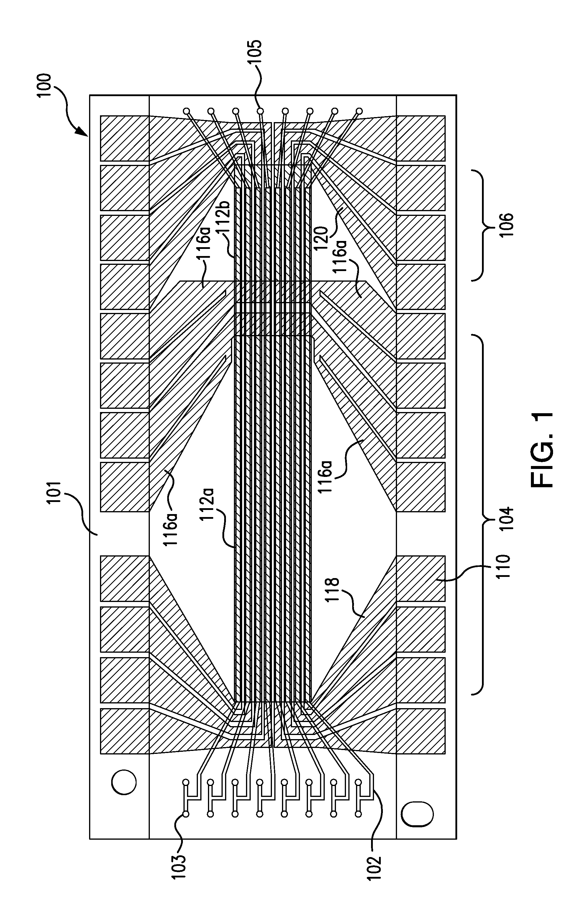
[0039]FIG. 1 illustrates a microfluidic device 100 that may be used in performing aspects of the present invention. It will be appreciated by those of skill in the art that other devices (including other m...


PUM

PropertyMeasurementUnit
temperatureaaaaaaaaaa
thermal responseaaaaaaaaaa
temperatureaaaaaaaaaa

Abstract

The present invention, in one aspect, provides a method for calibrating thermal control elements in situ using a single compound calibrator. In some embodiments, the present invention uses a compound calibrator to calibrate thermal control elements on a microfluidic device. In non-limiting embodiment, the compound calibrator can be a droplet, plug, slug, segment or continuous flow of any appropriate solution that, when heated, yields a thermal response profile with a plurality of features (e.g., maxima, minima, inflection points, linear regions, etc.).

Description

CROSS-REFERENCE TO RELATED APPLICATION[0001]The present application claims the benefit of priority to U.S. provisional patent application Ser. No. 61 / 378,591, filed on Aug. 31, 2010, the entire disclosure of which is incorporated herein by reference.BACKGROUND[0002]1. Field of the Invention[0003]The present invention relates to systems and methods for calibrating thermal sensors. More particularly, aspects of the present invention relate to systems and methods for using a compound calibrator to calculate a relationship between temperature and an electrical characteristic of the thermal sensor for use in connection with calibrating thermal sensors.[0004]2. Description of the Background[0005]Devices for performing chemical, biological, or other reactions (e.g., a microfluidic device for performing polymerase chain reaction (PCR) amplification of DNA molecules, or a microfluidic molecular diagnostic platform that performs PCR on a patient sample and then uses the PCR product for genoty...

Claims


Application Information

Patent Timeline
Patent Type & Authority Applications(United States)
IPC IPC(8): G01K15/00
CPCG01K15/005G01K15/00G01K11/06B01L3/502715B01L7/525G01N1/44G01N35/00594B01L2200/147B01L2200/148B01L2300/0816G01N2035/00237G01N2035/00366
Inventor COURSEY, JOHNATHAN S.HASSON, KENTON C.
Owner CANON US LIFE SCIENCES INC
Learn More