Optical system, optical apparatus, and method for manufacturing optical system
a technology of optical system and optical apparatus, applied in the direction of optical elements, manufacturing tools, instruments, etc., can solve the problems of large variation in aberrations upon vibration reduction, and affecting the effect of optical surface reflection ligh
- Summary
- Abstract
- Description
- Claims
- Application Information
AI Technical Summary
Benefits of technology
Problems solved by technology
Method used
Image


Examples
example 1
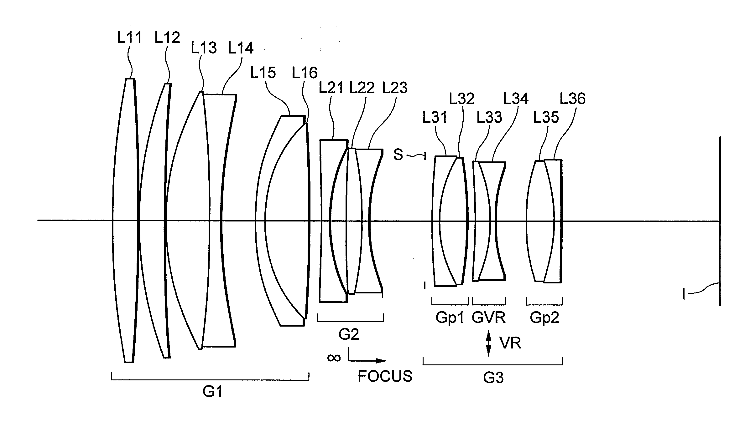
[0100]FIG. 1 is a sectional view showing a lens configuration of an optical system according to Example 1 of the present application.
[0101]The optical system according to Example 1 of the present application is composed of, in order from an object side, a first lens group G1 having positive refractive power, a second lens group G2 having negative refractive power, and a third lens group G3 having positive refractive power.
[0102]The first lens group G1 is composed of, in order from the object side, a double convex positive lens L11, a positive meniscus lens L12 having a convex surface facing the object side, a cemented lens constructed by a double convex positive lens L13 cemented with a double concave negative lens L14, and a cemented lens constructed by a negative meniscus lens L15 having a convex surface facing the object side cemented with a double convex positive lens L16.
[0103]The second lens group G2 is composed of, in order from the object side, a double concave negative lens...
example 2
[0122]FIG. 4 is a sectional view showing a lens configuration of an optical system according to Example 2 of the present application.
[0123]The optical system according to Example 2 of the present application is composed of, in order from an object side, a first lens group G1 having positive refractive power, a second lens group G2 having negative refractive power, and a third lens group G3 having positive refractive power.
[0124]The first lens group G1 is composed of, in order from the object side, a double convex positive lens L11, a positive meniscus lens L12 having a convex surface facing the object side, a cemented lens constructed by a double convex positive lens L13 cemented with a double concave negative lens L14, and a cemented lens constructed by a negative meniscus lens L15 having a convex surface facing the object side cemented with a double convex positive lens L16.
[0125]The second lens group G2 is composed of, in order from the object side, a double concave negative lens...
example 3
[0137]FIG. 6 is a sectional view showing a lens configuration of an optical system according to Example 3 of the present application.
[0138]The optical system according to Example 3 of the present application is composed of, in order from an object side, a first lens group G1 having positive refractive power, a second lens group G2 having negative refractive power, and a third lens group G3 having positive refractive power.
[0139]The first lens group G1 is composed of, in order from the object side, a double convex positive lens L11, a cemented lens constructed by a double convex positive lens L12 cemented with a double concave negative lens L13, and a cemented lens constructed by a negative meniscus lens L14 having a convex surface facing the object side cemented with a positive meniscus lens L15 having a convex surface facing the object side.
[0140]The second lens group G2 is composed of, in order from the object side, a double concave negative lens L21, and a cemented lens construct...
PUM
| Property | Measurement | Unit |
|---|---|---|
| Fraction | aaaaa | aaaaa |
| Fraction | aaaaa | aaaaa |
| Fraction | aaaaa | aaaaa |
Abstract
Description
Claims
Application Information
 - R&D
- Intellectual Property
- Life Sciences
- Materials
- Tech Scout
- Unparalleled Data Quality
- Higher Quality Content
- 60% Fewer Hallucinations
Browse by: Latest US Patents, China's latest patents, Technical Efficacy Thesaurus, Application Domain, Technology Topic, Popular Technical Reports.
© 2025 PatSnap. All rights reserved.Legal|Privacy policy|Modern Slavery Act Transparency Statement|Sitemap|About US| Contact US: help@patsnap.com